5.2 LEDs
The LEDs show the radio status, radio activity and LED states of your device. The LED states are made up of LED
combinations, further explained in detail in this chapter.
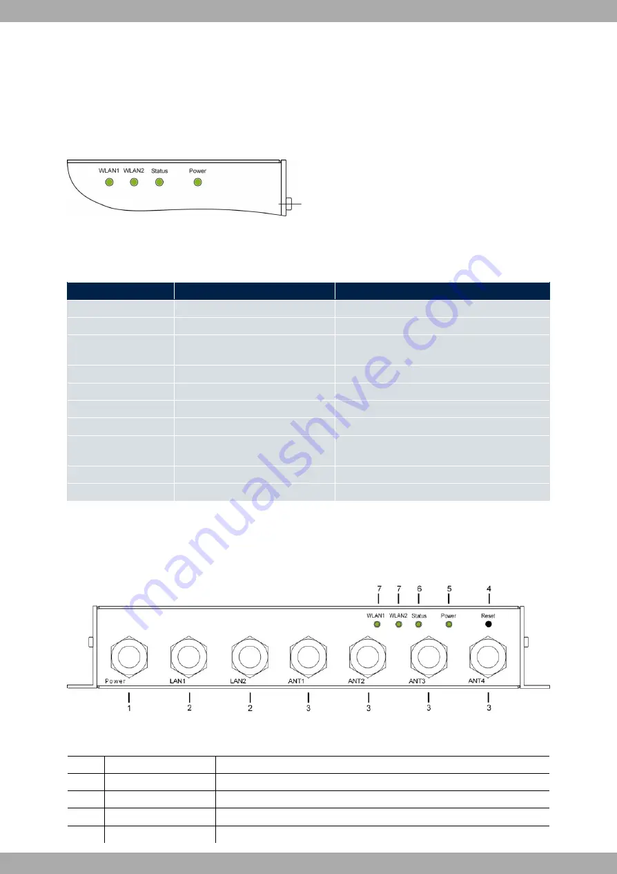
The LEDs on the APR222ac device are arranged as follows:
Fig. 6:
APR222ac
LEDs
In operation mode, the LEDs display the following status information:
LED status display APR222ac
LED
Status
Information
Power (green)
on
The power supply is connected.
off
No power supply.
Status (green)
off
The power supply is not connected. If other LEDs
are on, also Error.
on (static)
Error.
on (blinking)
Ready.
WLAN 1/2 (green)
on (blinking slowly)
Free.
on (static)
At least one client is registered.
on (flickering)
At least one client is registered and there is data
traffic.
on (blinking fast)
BLD (Broken Link Detection) active.
on (blinking fast)
5 GHz scan active.
5.3 Connectors
All the connections are located on the underside of the device.
Fig. 7: Connectors
Underside of APR222ac
1
Power
Socket for 110V DC or 24V DC power supply, depending on the model.
2
LAN1 / LAN2
10/100/1000BaseT (X) M12 (8-pin) Port.
3
ANT1 - ANT4
Connections to screw in the external antennas.
4
Reset
Reset button performs restart (base plate of the device).
5
Power
LED (green).
Teldat SA
5 Technical data
APR222ac
15


