I
Maintenance
—Type
3B5
Glass
Reed-Relay
Replacement.
The
glass
reed-relays
used
in
this
instrument are
pressurized. Therefore,
safety
glasses
should
be
worn
to
protect
the
eyes
when
replacing
these
relays.
To
avoid damage
to
the
reed-relays,
do
not
apply stress
to
the
metal-glass
bond.
When
it
is
necessary
to
bend a
lead,
use
two
pair
of
long-nose
pliers.
Before
replacing
a
reed-relay,
be
sure the
actuating circuit
is
not
at
fault.
See
the
Troubleshooting
procedure
for
methods
of
checking
the
circuit.
It
is
important
that
the
replacement
reed-relay
be correctly
positioned
within
the
drive
coil
assembly
with
about
the
same
lead
length
as
the
original
to
provide
similar
magnetic
characteristics.
REMOVAL:
1.
Observe
the
physical
position
of
the
leads
and
glass
bulb
of
the
old
reed-relay.
2. Cut
the
leads
of
the
old
reed-relay
at
the
bend in
the
lead.
This leaves
a
solder
post
for
installation
of
the
new
reed-relay
(those
which
have
three
leads
already
have
two
solder
posts
on
one
end;
unsolder
the
leads from these
posts).
3.
Pull
the
old
reed-relay
out
of
the
drive
coil.
REPLACEMENT:
1.
Slip
the
new
reed-relay
into
the
drive
coil.
If
the
reed
relay
has
three
leads,
slip
the single
lead
in
first.
2.
Position
the
new
reed-relay
in
exactly
the
same
physical
position
as
the
old one.
3.
Position
the
leads
correctly
and
solder
the
new
reed
relay
to the
solder
posts
(old
reed-relay
leads).
Avoid
exces
sive
heat
on
the
reed-relay;
use
a
heat-sink
on
the leads
if
soldering
close
to
the
glass
body.
4.
Clip
off
the
excess
lead
length
beyond
the
solder
posts.
Do
not
clip
the
leads
closer
than
1/
4
inch
from
the
glass body.
Rotary
Switches.
Individual
wafers
or mechanical parts
of
rotary
switches
are normally
not
replaceable.
If a switch
is
defective,
replace the
entire
assembly.
Replacement
switches
can
be
ordered
either
wired or unwired;
refer
to
the
Parts
List for
the
applicable
part
numbers.
When
replacing
a
switch,
tag
the
leads
and
switch termi
nals
with
corresponding
identification tags as
the
leads
are
disconnected.
Then,
use
the old switch
as
a
guide
for instal
ling
the
new
one. An
alternative
method
is
to
draw
a
sketch
of
the
switch
layout
and
record
the wire
color
at each
termi
nal.
When
soldering
to
the
new
switch
be
careful that
the
solder
does
not
flow
beyond
the
rivets
on
the
switch
termi
nals.
Spring tension
of
the switch
contact
can
be
destroyed
by
excessive
solder.
Access
to
Parts
Mounted on
Subpanel.
Many
of
the
components
mounted
on
the subpanel cannot
be
reached
easily
for
repair
or
removal
when the
instrument
is
fully
I
I
I
I
I
I
I
I
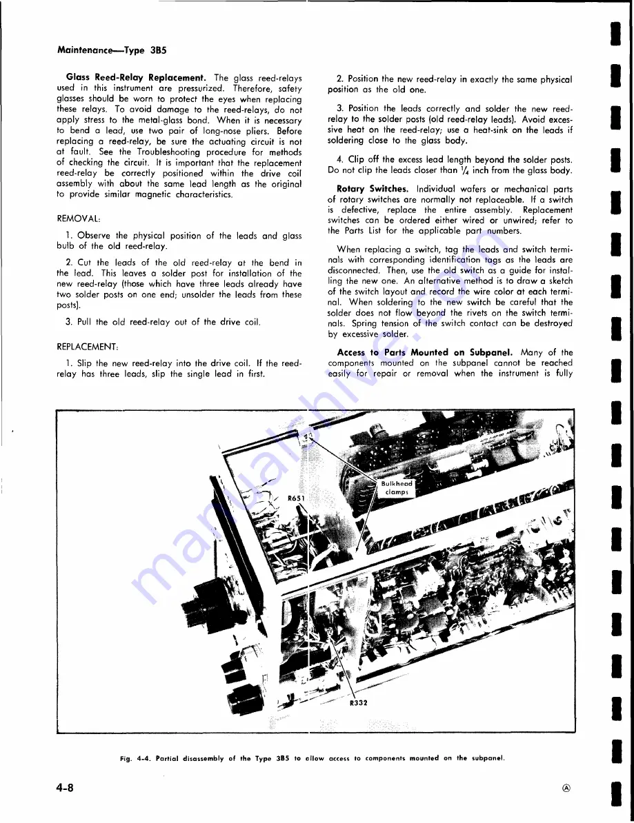
Fig.
4-4. Partial disassembly of the Type 3B5 to ollow access to components mounted on the subpanel.
I
I
I
I
I
I
I
I
I
4-8
Summary of Contents for 3B5
Page 4: ...Fig 1 1 Type 3B5 Automatic Programmable Time Base unit Type 3B5...
Page 15: ...Operating Instructions Type 3B5 TYPE 3B5 CONTROL SET UP CHART Fig 2 2 Control set up chart 2 7...
Page 48: ...CO I o Fig 3 13 Delay and Timing Circuit logic block diagram Circuit Description Type 3B5...
Page 61: ...GO i GO GO Fig 3 22 Seek Ciicuit Logic block diagram Circuit Description Type 3B5...
Page 70: ...u k KJ Fig 3 29 Circuit conditions for Manual Mode operation Circuit Description Type 3B5...
Page 71: ...w K w Fig 3 30 Circuit conditions for Seek Mode operation Circuit Description Type 3B5...
Page 72: ...w I u U Fig 3 31 Circuit condition for External Mode operation Circuit Description Type 3B5...
Page 88: ...Maintenance Type 3B5 Fig 4 9 Location of components on Logic Card 4 14...
Page 89: ...u Oi Fig 4 10 Location of components on Counter Card Maintenance Type 3B5...
Page 92: ...NOTES I...
Page 104: ...NOTES...
Page 106: ...Calibration Type 3B5 Fig 6 1 Recommended calibration equipment...
Page 160: ......
Page 176: ...J400 RtADOUT BOARD 3B5 PLUG IN A READOUT...
Page 182: ...397 R E A D O U T B O A R D 10 6b READOUT BOARD...
Page 184: ...FIG 1 FRONT SWITCHES TYPE 3B5 AUTOMATIC PROGRAMMABLE TIME BASE...
Page 185: ...FIG 2 CHASSIS REAR 3 GS to TYPE 3B5 AUTOMATIC PROGRAMMABLE TIME BASE...
Page 186: ...OPTIONAL ACCESSORIES...


