Configuration Setup
Edit Stations
Occasionally, depending on system requirements, some changes will need to be made to the default sta-
tions. Most commonly, SF122s may have been installed on point 1 of the facility’s room controllers,
PM123s may need to be set up as
Aux Input 1
,
Aux Input 2
, or
Aux Check In
functions using the Func-
tions drop-down menu, or SF123s may need to be programmed as reset buttons using the
Function
drop-
down menu.
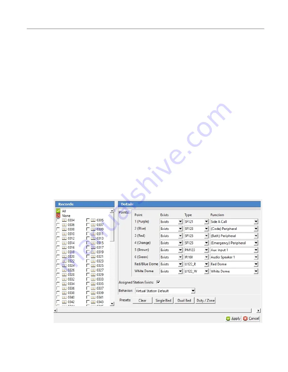
Select
Points
in the page selection pane of the Config Tool. Click
Edit Multiple
in the details pane to
open the
Edit Multiple
window.
Referring to the completed programming worksheet created during installation, select the stations to be
edited. Choose a group of stations that are wired the same way. If there are multiple wiring con-
figurations on the system, break the stations into groups, e.g., Wiring Configuration A, B, C, etc. Select
all of the wiring configuration A stations and edit them, then select all of the wiring configuration B sta-
tions and edit them, etc. Once the edit multiple window is open, select the Station IDs to be edited.
Once stations are selected, enable the points that have stations connected and choose the correct station
type and behavior. Mark any unused points as disabled.
Ensure that both the Red/Blue and White domes are marked as
Exists
. Select
LI122_R
if the room con-
troller has red LEDs or
LI122_B
if the room controller has blue LEDs. If the station must be set up as a
duty station or a zone light, change the behavior of the red/blue and white domes to Red or Blue Zone
Dome and White Zone Dome respectively. This will enable the Station ID to watch zones on the system
and annunciate a call when needed.
The
Single Bed
,
Dual Bed
, and
Duty/Zone
buttons at the bottom of the
Edit Multiple
window can be
used to quickly set up the default station connection points.
Ensure that the
Virtual Station Exists
box is checked. This will automatically enable the Station ID
selected and simplify future editing.
Once all selections have been made, click the
Apply
button. Repeat the edit multiple process for all wir-
ing configurations.
Figure 19 - Editing Stations
28
|
IL992 Tek-CARE120 Installation Manual
Copyright
©
TekTone Sound and Signal Mfg., Inc. All Rights Reserved


