65
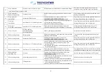
Once the dosing pump flow has been set, you have to check the setting of Dosing Timer parameter on the parameter
programming page of the Main Control Box (refer to
Main page
section). If the parameter setting value does not match that
reported on the attached Test Report (refer to the table below) adjust the parameter setting value (refer to
Main page
section).
Model
Valve Regulation
(%)
Timer
*
(sec.)
ECOmar 20 S
40 %
26
ECOmar 32 S
40 %
40
ECOmar 45 S
40 %
50
ECOmar 70 S
54 %
60
ECOmar 145 S
54 %
137
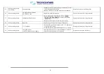
Table 14.3.1 – H
2
O
2
dosing pump regulation and settings table
14.3.2
ECOFLOC Dosing pump setting
Before operating the ECOFLOC dosing system, it is recommended to check the correct setting of its dosing pump, verifying
that the pump flow regulation matches the value reported on the attached Test Report. If pump flow regulation need adjustment,
operate on the pump control panel (refer to figure on previous section); performing a dosing pump flow regulation procedure.
To perform a dosing pump flow regulation procedure follow the steps listed below:
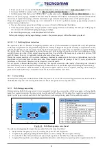
Make sure that the pump is power, by checking the power on LED (8) ignition;
Stop the dosing pump by pushing the STOP button (1), if it is running otherwise ignore this step;
Press the 100% flow full-scale button (2) and verify the ignition of the 100% flow full-scale LED (5);
Set pump flow regulation, according to supplied model (refer to table below) by operating on flow regulation knob (10).
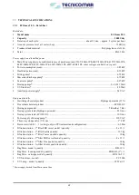
Once the dosing pump flow has been set, you have to check the setting of Dosing Timer parameter on the parameter
programming page of the Main Control Box (refer to
Main page
section). If the parameter setting value does not match that
reported on the attached Test Report (refer to the table below) adjust the parameter setting value (refer to
Main page
section).
Model
Valve Regulation
*
(%)
Timer
*
(sec.)
ECOmar 20 S
21 %
26
ECOmar 32 S
21 %
40
ECOmar 45 S
21 %
50
ECOmar 70 S
27 %
60
ECOmar 145 S
27 %
137
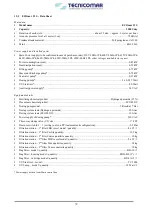
Table 14.3.2 – ECOFLOC dosing pump regulation and settings table
14.3.3
Display Contrast Calibration
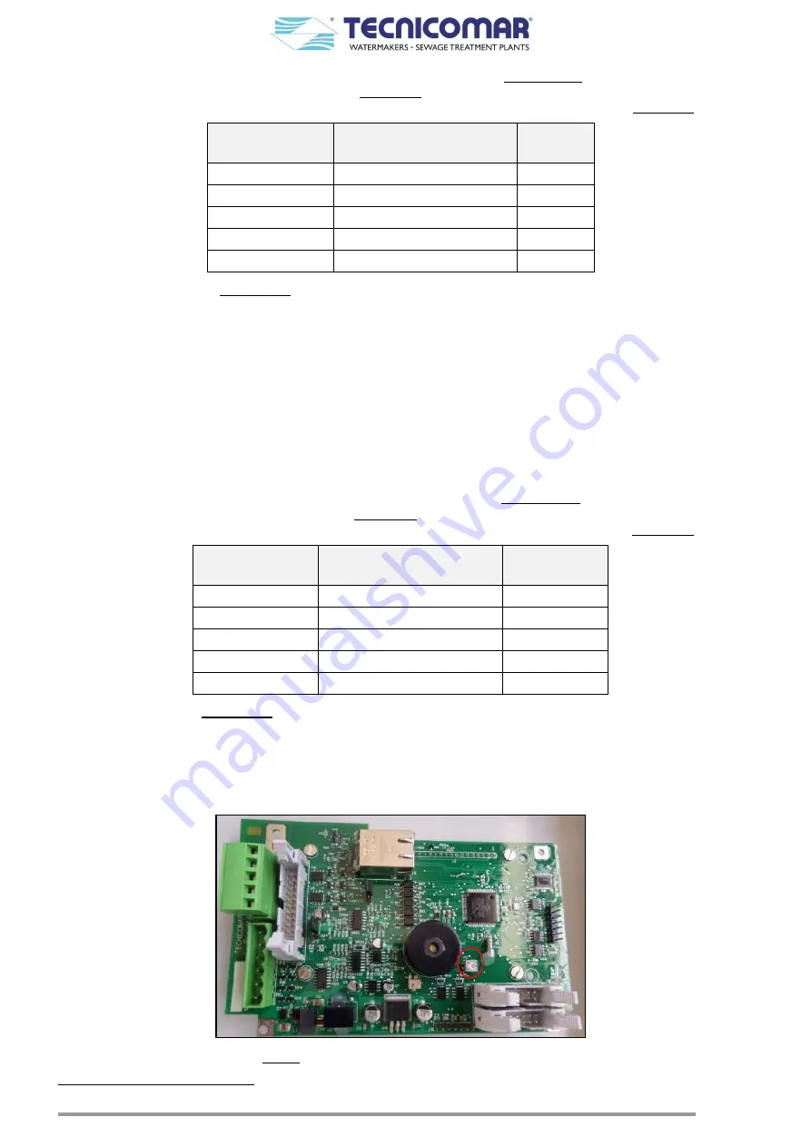
To calibrate the contrast of ECOmar S STP display; it is necessary to operate through a suitable screwdriver on the trimmer
P2, installed on the rear side of PRO14 printed circuit board of the Main Control Box cover, to optimize the display visibility.
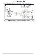
Fig. 14.3.3 (Trimmer P2 on PRO14 P.C.B. rear side)
*
Refer to attached Test Report


