


29
DANGER:
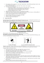
U.V. lamps are fragile and can cause serious injury when broken. Consequently they must be handled
with care, protecting the hands by wearing gloves that guarantee adequate protection. They also contain considerable
amounts of mercury and must be disposed of in observance of the laws in force.
WARNING:
Avoid touching the quartz of the lamp with your fingers so that greasy finger marks are not left on it. If
this occurs, clean it using a soft cloth and alcohol.
Tighten each PVC collar onto the corresponding pressure nozzle. Tighten each cable gland onto the corresponding collar,
ensuring that you do not twist the cable.
Finally open each sump of the supplied safe filter and check that the bag cartridge is installed and in good conditions, if not
install a new bag cartridge on each sump of the supplied safe filter.
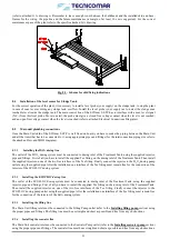
8.7
Outboard discharge line
The treated clarified water discharge takes place through the U.V. Sterilization System outlet. The discharge outlet is provided
with threaded discharge outlet. The overboard discharge must be installed below the waterline, and it is necessary to install the
discharge anti-siphon valve set, placed 20-30 cm above the waterline, between the discharge line. It is also possible to directly
install the overboard discharge 20-30 cm above the waterline, but it is not recommended.
8.8
Electrical connections
8.8.1
Main Control Box
The external main power supply (your supply) has to be brought into the Main Control box and connected (refer to attached
Electrical Connections diagrams) to the “power supply” terminal inside it, by a cable equivalent to those described in the table
below. Moreover, when the plant is supplied with the standard (
1 Tank Control
) configuration for the 3 phases power supply,
an auxiliary power supply 230 V AC (your supply) has to be brought into the Main Control box and connected (refer to attached
Electrical Connections diagrams) to the proper terminals inside by a cable equivalent to those described in the table below.
We recommend to assign the power connections to skilled personnel and that the power supply line be disconnected
during the work.
A safety cut-out switch in the main panel is recommended just for the electrical consumption of the unit.
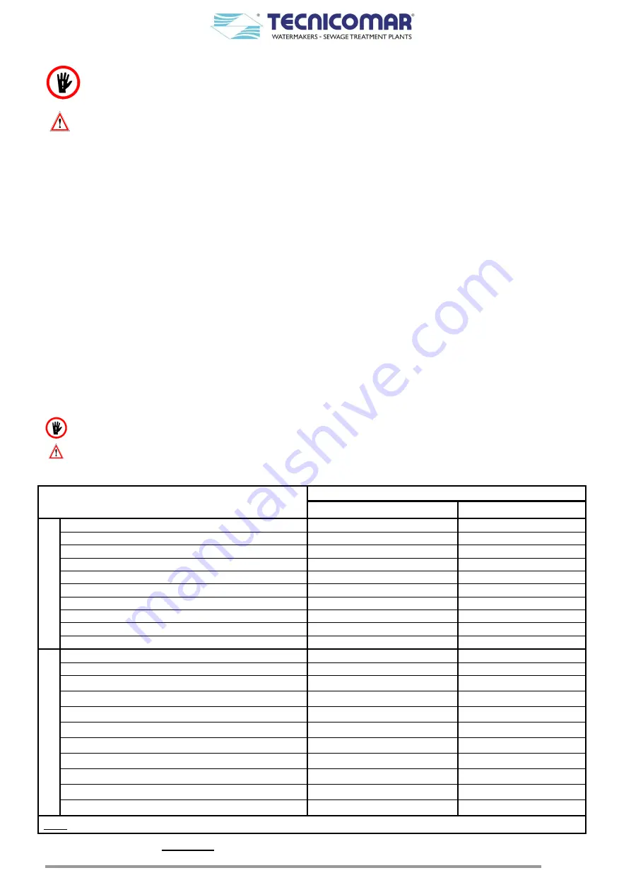
Main Control Box has also to be connected to all loose supplied parts using the proper cables as described in the table below.
ELECTRICAL CONNECTION TO THE
MAIN CONTROL BOX
CABLE TYPE
ECOmar 20-32 S
ECOmar 45-145 S
2
3
0
V
s
in
g
le
-pha
se
MAIN POWER SUPPLY (ns)
FROR 3G2.5mm
2
FROR 3G4mm
2
SEA WATER PUMP (s)
FROR 3G1.5mm
2
FROR 3G1.5mm
2
FILLING PUMP (s)
FROR 3G1.5mm
2
FROR 3G1.5mm
2
H2O2 DOSING SYSTEM (s)
FROR 3G1mm
2
FROR 3G1mm
2
ECOFLOC DOSING SYSTEM (s)
FROR 3G1mm
2
FROR 3G1mm
2
SLUDGE DISCHARGE VALE (V2) (s)
FROR 3x1mm
2
FROR 3x1mm
2
U.V. STERILIZER (s)
FROR 3G1mm
2
FROR 3G1mm
2
LEVEL PROBE CONTROL BOX (s)
FROR 3x1mm
2
FROR 3x1mm
2
REMOTE CONTROL (supplied 15m)
4x0.5mm
2
4x0.5mm
2
MAX. LEVEL OF SLUDGE TANK–NC (ns)
FROR 2x1mm
2
FROR 2x1mm
2
2
3
0
/4
0
0
V
t
h
re
e-
pha
se
MAIN POWER SUPPLY (ns)
FROR 4G2.5mm
2
FROR 4G4mm
2
AUX. POWER SUPLLY 230 V AC (ns)
FROR 3G1.5mm
2
FROR 3G1.5mm
2
SEA WATER PUMP (s)
FROR 4G1.5mm
2
FROR 4G1.5mm
2
FILLING PUMP (s)
FROR 4G1.5mm
2
FROR 4G1.5mm
2
H2O2 DOSING SYSTEM (s)
FROR 3G1mm
2
FROR 3G1mm
2
ECOFLOC DOSING SYSTEM (s)
FROR 3G1mm
2
FROR 3G1mm
2
SLUDGE DISCHARGE VALE (V2) (s)
FROR 3x1mm
2
FROR 3x1mm
2
U.V. STERILIZER (s)
FROR 3G1mm
2
FROR 3G1mm
2
LEVEL PROBE CONTROL BOX (s)
FROR 3x1mm
2
FROR 3x1mm
2
REMOTE CONTROL (supplied 15m)
4x0.5mm
2
4x0.5mm
2
MAX. LEVEL OF SLUDGE TANK-NC (ns)
FROR 2x1mm2
FROR 2x1mm
2
Note:
ns
:= not supplied;
s
:= supplied standard (= 3 meters)
Table. 8.8.1 - Sizing of the cables for Main Control Box connection