


-
OPERATORS MANUAL
Page 18
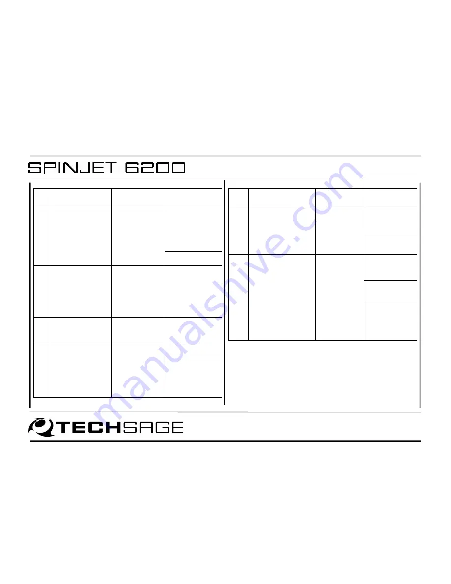
No.
Problem
Most probable
cause
How to solve
problem
a. Turn off
SPINJET. Check
Media path and
remove any
Media. Turn on
SPINJET.
4
Flashing yellow
INFO LED switching
on and Error 07-09
indicated on
Designjet control
panel.
Media Jam or
Inoperative
Feeder System
b. Call service.
a. Check SPINJET
power.
b. Check harness
between SPINJET
and Designjet.
5
“Communication
with Media bin”
Error indicated on
Designjet control
panel.
Connection
between SPINJET
and Designjet
has been lost.
c. Call service.
6
The SPINJET does
not go through
Initialize when
powering up.
Inoperative
Control box.
Call service.
a. Set DUPLEXER
to YES
b. Check harness
between SPINJET
and Designjet.
7
The SPINJET will not
enter Ready state
when Initializing
Printer. SPINJET is
in upper position.
Connection
between SPINJET
and Designjet
has been lost.
c. Call service.
No.
Problem
Most
probable
cause
How to solve
problem
a. Use media
according to
specified quality
parameters.
8
Print head collides
with media when
Designjet is preparing
to print page 2.
Improper
media quality
with too much
curl after
printing of first
page.
b. Adjust ink
reduction and/or
margins.
a. Use media
according to
specified quality
parameters.
b. Adjust ink
reduction and/or
margins.
9
Printer loads but then
ejects page 1 without
printing page 2.
Sheet position
tolerances of
the printer
exceeded
because of
unsuccessful
sheet capture
or feed
c. Check that
Media Roll is
installed correct
(see
3.1
Loading
Media
).


