


Service guide
March 2001
15
2.4 Control system
components
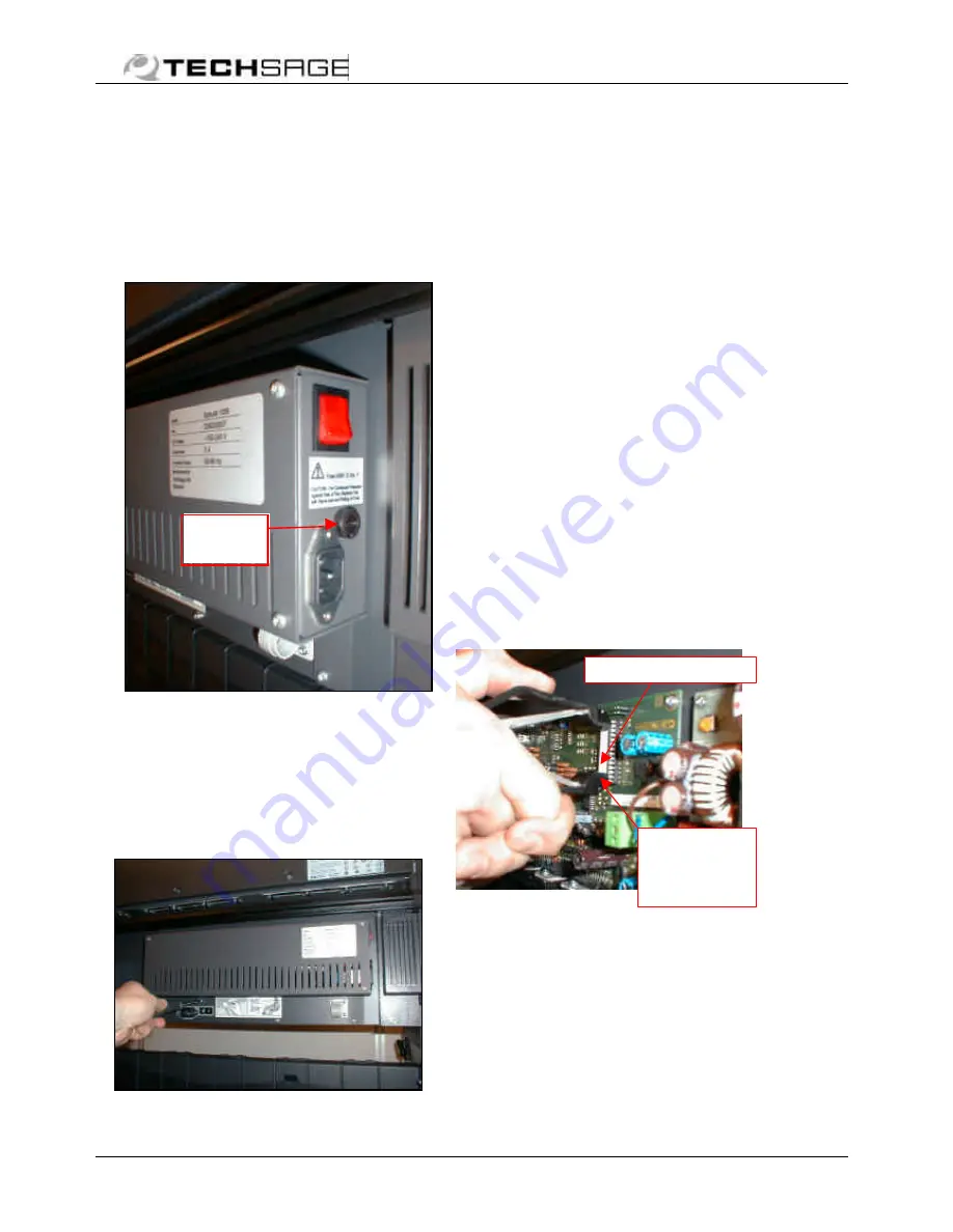
5551 073 Fuse
5551 088 Fuse holder cap
Turn fuse cap with screwdriver
and remove fuse and cap. Replace
with fuse rated “250V 3.15A T
(ø5 x 20 mm) only!
5550 032 Assy, control
system
Disconnect all harnesses before
removal. Control box is fastened
to printer by 2 screws below box.
Reconnect as described in
installation guide (male/female
coding makes it impossible to
interchange the two 15-pin
connectors).
5550 048 PIC, programmed
Component safety precautions
Handling:
•
Avoid touching the legs,
which are susceptible to
static electricity
•
Keep the legs mutually
“grounded” with conductive
material for storing/shipping
Exchange:
Note the position of the half-circle
notch on the body of the PIC: It
should be pointing downwards in
the control box when mounted on
the printer.
Before replacement switch off
power completely by removing the
supply cord. Replace the PIC
using a PIC extractor (tool) as
shown in picture.
Especially if tool is unavailable,
take care to lever out and install
the PIC as parallel as possible,
thus avoiding bending of the legs.
Fuse
holder
PIC,
programmed
Take hold of
both ends
with the PIC
extractor


