background image

CAN bus and IR-CAN infrared interface 

The IR-CAN interface (infrared CAN) offers a simple way of transferring functional data. It is 
located under the two buttons of the UVR1611 and on the lower side of the bootloader case. 
During the data transfer, the bootloader must lie in the correct position on the controller: 
Bootloader – upper edge = Controller display – lower edge, the sideways position of the 
display is marked on the bootloader. 


For transferring the functional data the controller must be prepared via the 

"Datenverwaltung" 

("data administration")

 menu. This is only permitted in expert mode. The controller switches to 

data transfer mode when the "

Upload

 bzw. 

Download wirklich starten?

" ("

Really start upload


or 

download?

") query is confirmed. After this, the bootloader is placed in the correct position 

on the controller (at the lower edge of the display and between the markings). As with the 
CAN cable, the data transfer is started by pressing the Start button on the bootloader. The 
green LED flashes during the transfer and the functional data takes about 15 seconds to 
transfer. 


Since an operating system can take about 5 minutes to transfer, this should always be 
done via a CAN bus cable connection

. If the loading of the operating system is interrupted 

then a renewed transfer is only possible via a cable connection!  


In addition to data transfer, the ethernet interface of the CAN bus also allows direct access to 
the CAN network devices via a browser on the PC. Both LEDs flash briefly when the CAN 
cable is plugged in and after about 20 seconds, the green LED lights up to indicate that the 
BL-NET is ready to operate on the CAN bus. 


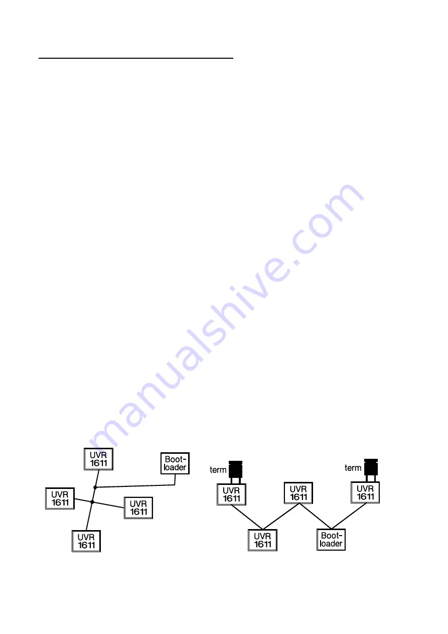
When using the CAN bus to connect several devices with a total cable length above 5 m, 
correct termination of the bus is important. The network

 terminators

 must be connected at 

the 

cable ends

. The lower side of every controller, and the bootloader, have a corresponding 

jumper bridge (

term

) for this. A CAN bus must never be connected from a node (terminal) to 

other devices in a star formation. The correct layout is a series cable from the first device 
(with terminator) to the second device, then the third, etc., and the last bus connection must 
also have a termination jumper. 
Additional information on the correct layout of a CAN bus network (e.g.: cable selection, etc.) 
is provided in the UVR1611 controller handbook. 


Wrong 

             Right 


Summary of Contents for BL-NET

Page 1: ...bootloader itself using the software provided on the homepage at www ta co at Data logging of the temperature and output statuses of all UVR controllers and various other measurements such as rotation...

Page 2: ...ting system upload PC bootloader 26 Transfer of bootloader data 27 Troubleshooting 28 Connecting the BL NET to a LAN network 29 Accessing the BL NET via a browser 33 Accessing Hauptmenue main menu pag...

Page 3: ...a download BL UVR1611 46 Operating system download BL UVR1611 47 Data transfer via ethernet using a browser 48 Troubleshooting data transfers 48 Online Schema online scheme 49 Creating a graphic for t...

Page 4: ...e the BL NET from the PC after a successful data transfer to avoid un wanted activation of the bootloader from the PC and ensure long battery life Data line Every UVR controller has a data line output...

Page 5: ...connection NETZW EG DL ja yes which is then handled by the bootloader as a second virtual UVR1611 Logging of network variables is thus not possible when two physical controllers are connected to the...

Page 6: ...ce an operating system can take about 5 minutes to transfer this should always be done via a CAN bus cable connection If the loading of the operating system is interrupted then a renewed transfer is o...

Page 7: ...a green LED that indicates an ethernet connection to another device and a red LED that indicates data transfer The bootloader requires a fixed IP address because it does not support DHCP See also the...

Page 8: ...versions This only then removes the application and all data created with the application is retained CAUTION Newer software versions are not always compatible with the version of the boot loader oper...

Page 9: ...re it can be replaced with a new version Installation 1 When a bootloader or D LOGGUSB is connected to the PC with a USB cable the PC automatically recognises a new hardware component and automaticall...

Page 10: ...er for the device Windows XP Software von einer Liste oder bestimmten Quelle installieren install software from a list or other source Windows Vista Auf dem Computer nach Treibersoftware suchen search...

Page 11: ...nstalled 5 Clicking Fertig stellen finish completes the installation of the USB controller driver 6 The Hardware Assistent Hardware Wizard proceeds with the installation of the virtual COM port driver...

Page 12: ...te Manager device manager Windows 98 Start Einstellungen settings Systemsteuerung control panel System Ger te Manager device manager Anschl sse ports COM and LPT Windows 2000 XP classic view Start Ei...

Page 13: ...bootloaders must be disconnected from the PC before the driver can be deinstalled Select the driver software FTDI USB Serial Converter Drivers in the list of installed programs and then remove it Wind...

Page 14: ...nt devices SETUP The setup contains the settings required for correct communication between the PC and the bootloader The Test Com command allows an automatic search for the bootloader at the COM port...

Page 15: ...IP has the same function as Test COM but for the ethernet connec tion Test IP only returns a valid result when the ethernet interface of the BL NET has already been parameterised and the IP address an...

Page 16: ...difference A save criterion of 3K is recommended for fault analysis purposes A data record is saved every time a measured temperature changes by more than 3K or when an output state changes The maximu...

Page 17: ...ata storage of the bootloader but in the customer mode it is possible to specify that the data in the bootloader is retained If a power failure occurs when logging data from controllers that do not ha...

Page 18: ...formats This allows the creation of graphics and statistics using the recorded measurements To adjust the generated table to suit the language specific requirements a comma or a full stop can be spec...

Page 19: ...ed data cannot be acquired on site then the measurements can be acquired as follows Preparation of the data logging 1 Connect the bootloader to the PC without using a DL connection power supply via CA...

Page 20: ...is already being used by another application this must be ended in order to communicate with the bootloader Multiple applications cannot access the interface at the same time The bootloader is not re...

Page 21: ...the cables must be laid separately or at least one cable must be shielded 5 To isolate data transfer problems with a single cable test the link using a short cable 1 metre 5 1 If the data transfer wor...

Page 22: ...onal data can also be copied in both directions data upload and download Setup The setup contains the settings required for correct communication between the PC and the bootloader Saves the set interf...

Page 23: ...he BL NET the storage is large enough to save both the logged data and the system data at the same time Selection of the standard directories Memory Manager language selection The menu is used for con...

Page 24: ...e PC to the bootloader The bootloader has 7 memory positions for functional data which allows the simultaneous storage of different sets of func tional data The left column shows the data that is curr...

Page 25: ...in the bootloader is shown in the left column Setting a tick in the save field allows specification of the path and name of the file on the PC where the functional data is to be stored Clicking Start...

Page 26: ...d operating system prg on the PC is selected with the select firmware button When uploading an operating system for a UVR1611 a user defined welcome page for the controller can also be defined If a we...

Page 27: ...ting system update PC bootloader The latest BL NET operating system can be downloaded from http www ta co at CAUTION Newer operating systems are not necessarily compatible with the software already pr...

Page 28: ...t be ended in order to communicate with the bootloader Multiple applications cannot access the interface at the same time The bootloader is not recognised by the Memory Manager Test Com function 1 Mak...

Page 29: ...terfaces COM 1 to COM 6 5 If a BL NET is found the interface can be automatically adopted in the setup via Take over and the setting can be saved via Save If the software does not find a BL NET then e...

Page 30: ...ddress 192 168 10 200 is free Since the ping command above received an answer the IP address 192 168 10 200 is already assigned to a device in the network and cannot be used for the BL NET A new attem...

Page 31: ...each bootloader must be assigned a different BLD number HTTP port The port used to access the bootloader via a browser can be set to any desired value default is port 80 Communication between Winsol a...

Page 32: ...Since several bootloaders can be connected in a LAN network this infor mation must be specified again in the software Winsol or Memory Manager in order to address the correct BL NET 12 The ethernet co...

Page 33: ...uring that the latest version of the pages is always displayed Accessing Hauptmenue main menu page Entering the IP address of the BL NET into any browser will display the BL NET main page Example At p...

Page 34: ...NET Events can also be defined that cause the bootloader to send an SMS when they occur A GSM module is essential for all these functions Ethernet Konfiguration ethernet configuration The ethernet se...

Page 35: ...mum of eight characters with no special characters Password rules The passwords can only be changed after loading the factory settings or as an Experte expert user The expert password can only be dele...

Page 36: ...red to accept cook ies The corresponding password can only be entered after the desired entry level has been selected An incorrect password causes the login page to be redisplayed After entry of the c...

Page 37: ...Select the desired aktive Knoten active node and click the button The link button Men seite laden load menu page is used to access the nodes The menu page of the device is then displayed UVR1611 menu...

Page 38: ...rameters After selecting a value this is immediately transferred to the controller via the CAN bus The controller stores the parameter and then returns the corrected information page which is then red...

Page 39: ...ct the transfer direction of the functional data Select the memory position of the Funktionsdaten functional data or Betriebssystem operating system the name of the data is displayed next to the memor...

Page 40: ...rticular telephone numbers An integrated GSM module is required for all these functions and this module can be retrofit ted if required All settings for the GSM module and SMS communication can be mad...

Page 41: ...llow configuration of the CAN network inputs outputs of the bootloader whose status can be queried via SMS An optional Ereignis event can be defined for every network input for which the BL NET automa...

Page 42: ...the first telephone number Abfragen Gruppen group queries This menu allows the definition of groups in order to allow querying of entire blocks of data via a group designation instead of just queryin...

Page 43: ...it time Normal Abgesenkt re duced and intern internal can be used to change the operating mode of a heating circuit via SMS To do this the corresponding parameterised analogue network input of the UVR...

Page 44: ...network Changes do not take effect until the Neus tart restart of the BL NET NOTE The commonly used subnet mask of 255 255 255 0 means that when an IP address is assigned where the first three numbers...

Page 45: ...the lower edge of the UVR display Display side edges are marked with DISPLAYPOSITION UVR1611 on the BL NET NODE 63 Data transfer of the operating system and functional data is always performed by the...

Page 46: ...TA BOOTLOADER Upload Data CONTR BOOTLD Download Data BOOTLD CONTR Download Data BOOTLD CONTR select BOOTLD CONTR DATA SOURCE Bootld Storage Point 1 TARGET Controller Functional Data Overwrite yes Fact...

Page 47: ...ATION OPER SYSTEM BOOTLD Download Oper System BOOTLD CONTR Download Oper System BOOTLD CONTR select BOOTLD CONTR DOWNL OPERAT SYSTEM REALLY START yes WARNING Use Cable Wiring The controller switches t...

Page 48: ...gin again READY FOR DOWNLOAD As long as the operating system has not been fully loaded into the UVR1611 the controller has no other functionality Pressing the START button on the bootloader starts the...

Page 49: ...ning the appearance of the page is required for displaying the online scheme The HTML file can be easily created using the TAPPS program TAPPS creates the required HTML file based on graphical positio...

Page 50: ...rk inputs The network inputs can be defined using a browser in the GSM Einstellungen GSM settings menu of the BL NET see the relevant chapter Analogue input a0 af Analogue network inputs 1 16 Digital...

Page 51: ...green LED lights up The factory settings include the following parameters CAN bus Node No 62 Ethernet IP address 192 168 0 1 Subnet mask 255 255 255 0 Gateway 192 168 0 1 BLD No 0 HTTP port 80 TA por...

Page 52: ...Technische Alternative elektronische Steuerungsger tegesellschaft mbH A 3872 Amaliendorf Langestr 124 Tel 43 2862 53635 Fax 7 www ta co at 2008...

Reviews: