3-2
EO18-33006
3. INSTALLATION PROCEDURE FOR OPTIONAL EQUIPMENT
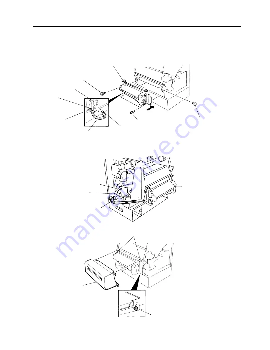
6) Install the cutter unit with the attached four screws (cutter attaching screw, SM-4x6C and
FL-4x6).
7) Connect the cutter harness to CN1 on the cutter I/F PC board through the opening of the cutter unit.
Cutter Unit
Screw (SM-4x6C)
Cutter Unit
Connector (CN1)
Opening
Cutter Harness
Cutter I/F PC Board
Cutter Attaching Screw
Screw (FL-4x6)
Fig. 3-2
3.1 CUTTER MODULE (B-4208-QM)
9) Mount the cutter cover with the two screws.
I/O PC Board
Cutter Cover
Cutter Harness
Cutter Unit
Fig.3-3
Cutter Attaching Screw
Fig. 3-4
Screw
8) Connect the cutter harness to the CN4 on the I/O PC board.
CN4


