46
131
68
124
APPLY CHASSIS
TAPE (162) HERE
185
4
4
185
33
107
58
23
133
81
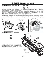
BAG E (Continued)
25
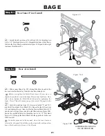
Figure 61
q
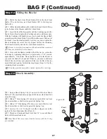
1. Install the Battery Mount Posts (68) to the Chassis (46), as
shown, by placing the square base of the Post in the countersunk
pockets on the drivers right side of the Chassis.
q
2. Thread a 4-40 x 3/8" Cap Head Screw (131) through the bottom
of the Chassis into each of the Battery Mounting Posts and tighten.
q
3. One Body Clip (124) will be inserted into the holes on the top
of each Battery Post at a later step in this manual.
q
4. Peel the backing off the Battery Insulation Tape (162) and
allign the cut-outs in the tape with the appropriate placeson the Chas-
sis and apply the Tape to the Chassis as indicated in Figure 61.
Step E-12
Battery Post Install
q
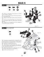
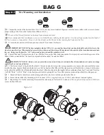
1. Place a "Foam Thing" (185) over the Ball Stud (107) in the left
rear Hub Carrier (23). Place a second "Foam Thing" over the Ball Stud
(33) in the rear Shock Tower (58).
Assure that the drive end of the CVD Bone is inserted in the
Outdrive before attatching the Tierod.
q
2. Snap the end, closest to the groove, of the Turnbuckle to the
Ball Stud in the left rear Hub Carrier. Snap the other end to the Ball
Stud in the rear Shock Tower. Repeat Steps 1-2 to attach the other
Tierod assembly to the right rear Hub Carrier (24) assembly.
Assure that the grooves on all of the rear Turnbuckles are
located on the drivers left-hand side for easier adjustment later.
Step E-11
Rear Camber Tierod Install
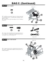
Figure 60
131
Step E-10
Swaybar Link Assembly
Figure 59B
Figure 59A
q
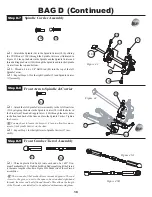
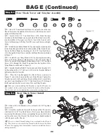
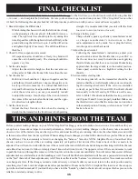
1. Thread a Plastic Rod End (4) onto each end of a 4-40 x 5/8" Set
Screw (137). Tighten both sides equally until the Rod is the same
length as the one shown in Figure 59B. Make two of these assem-
blies.
137
4
162

