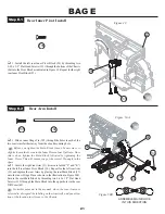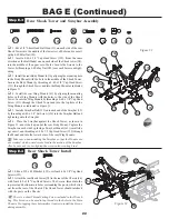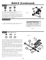
q
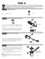
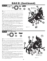
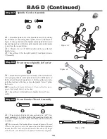
1. Slide the Tensioner Arm assembly (110) down over the Belt (77) and connect the slot in the Tensioner Arm with the Slipper Clutch
assembly's Belt Tensioner Bushing (96) as indicated in Figure 26A.
q
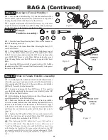
2. Slowly start rotating the Tensioner Arm assembly around the Belt Tensioner Bushing in a clockwise direction as shown in Figure 26B.
While rotating the Tensioner Arm assembly, slightly pull upward to keep the Tensioner Arm locked and rotating around the Belt Tensioner
Bushing. The Belt should be positioned between the Slipper Drive Pulley (70) and the Tensioner Arm.
q
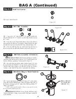
3. Place a #4 Hardened Washer (151) over a 4-40 x 5/16" Button Head Screw (146).
q
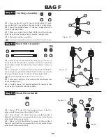
4. Once you have the belt wrapped around the Slipper Drive Pulley, and Belt Tensioner is in position, as shown in Figure 26C, secure the
Tensioner assembly by threading the 4-40 x 5/16" Button Head Screw, with Washer through the Chassis (46) and into the upper hole in the
Tensioner Arm. With the Screw about one turn loose, push down on the flat part of the Tensioner and set the desired Belt tension, tighten the
Screw.
The belt should move 1/8" (3mm) to 1/4" (7.5mm) up and down for the ideal tension.
46
145
61
77
70
44
BAG B (Continued)
Step B-8
Step B-7
11
q
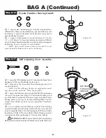
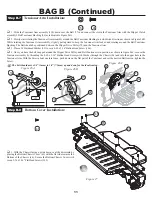
1. With the Chassis facing upside down, seal the drivetrain by
placing the Bottom Chassis Cover (61) with the flat side towards the
Bottom of the Chassis (46). Secure the Bottom Chassis Cover with
seven 2-56 x 3/16" Flat Head Screws (145).
Figure 27
Figure 26B
151
146
Tensioner Arm Installation:
Bottom Cover Installation:
145
96
77
110
46
110
151
146
Figure 26C
Figure 26A


