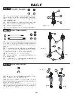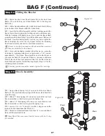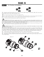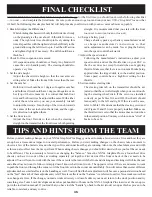
138
191
46
71
Wing (192)
Body (192)
BAG H (Continued)
33
Step H-7
Step H-8
q
1. Trim the Body (192) and Wing along the trim lines as shown.
q
2. Once the perimeter of the Body is cut, locate the three dimples
in the Body used for mounting (two in the front, and one in the rear)
and locate the dimple for the Antenna Tube. Drill each of them to
3/16" diameter holes.
q
3. Now locate the cooling scoop on the left side of the Body. Cut
out the lowest corner to allow air to cool motor.
q
4. Align the holes in the Body with the Body Mounts and attatch
the Body to the rolling Chassis using three Body Clips (124).
Figure 77
Figure 76B
Gear Cover Installation
Body Mounting
124
Figure 76A
q
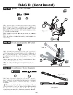
1. Locate the Gear Cover (191) and cut the bottom side of it along
the trim line as shown in gray in Figure 76B. Drill three 1/8" mounting
holes in the Gear Cover at the three locations marked with dimples.
q
2. Place the trimmed Gear Cover over the Spur Gear (71) and
secure it with three 4-40 x 1/4" Button Head Screws (138) through the
three open holes in the top of the Chassis (46).
You may opt. to run the ESC wires through the Gear Cover with
the small cut-out on the bottom of the Gear Cover shown in Figure
76A. If you will be running the wires over the Gear Cover you should
leave that material there.
138
It is recomended that you
do not
run the ESC wires through the
Gear Cover when running your XXX-4 G+ in extrememly dusty con-
ditions.

