77
29
46
116
110
152
44
98
146
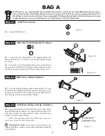
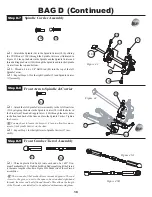
Step B-2
q
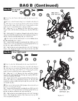
1. Snap a 3/16" x 3/8" Bearing (116) into the right side of the Idler
Pulley (44). The Bearing will snap past the ridge and stop.
q
2. Place the Idler Pulley Shaft (98) through the Idler Pulley from
the Bearing side.
q
3. Slide a #4 x .020 Washer (152) over the 4-40 x 5/16" Button
Head Screw (146).
q
4. Insert the 4-40 x 5/16" Button Head Screw through the Idler
Pulley and thread it into the Belt Tensioner Arm (110) positioned as
shown in Figure 20.
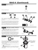
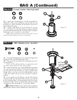
Figure 21
Figure 20
BAG B
8
152
116
146
98
q
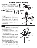
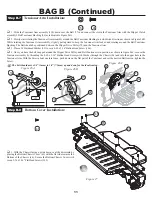
1. Position the Chassis (46) upside-down on your work bench.
Insert the Belt (77) and pull it through both ends of the Chassis.
q
2. Pull the Belt out, just slightly, through the bottom of the Chas-
sis and insert the Steering Tunnel (29), tall end forward, into the slot
in the front of the Chassis. Press into position as indicated in Figure
21.
The Steering Tunnel should now be located in between the
Belt, with the Belt still slightly hanging out of both ends of the car.
Step B-1
*NEVER PINCH THE BELT*
NEVER OVER TIGHTEN THE SCREWS IN THE
CHASSIS - Team Losi has designed interlocking
features into the XXX-4 G+ Chassis. Only tighten the
Screws to the point of being snug, so the parts are held
firmly in place.
Tensioner Arm Assembly:
Belt Installation:


