background image

MADE IN THE UNITED STATES OF AMERICA

    P/N  800-0208

4710 Gausti Rd., Ontario CA 91761

Phone: (909) 390-9595 / Fax: (909) 390-5356

www.TeamLosi.com  /  [email protected]

OWNER'S

MANUAL

Team losi, Division of Horizon Hobby inc.,


Carefully read through all instructions to familiarize yourself with the parts, construction techniques, and

 tuning tips outlined in this manual. Being able to grasp the overall design of your new XXX-4 

Graphite

              Plus

 Buggy before beginning the construction process will ensure a smooth assembly.

 Take your time and pay close attention to detail. Keep this manual for future reference.

10/01/2003

JAC/RWW

Summary of Contents for XXX4 Graphite Plus

Page 1: ...by inc Carefully read through all instructions to familiarize yourself with the parts construction techniques and tuning tips outlined in this manual Being able to grasp the overall design of your new...

Page 2: ...reference to the right or left side will relate to the direction of the helmet The kit is composed of different bags markedAthrough H Each bag contains all of the parts necessary to complete a particu...

Page 3: ...that is used will determine the final drive ratio To calculate the final drive ratio first divide the spur gear size by the pinion gear size For example if you are using a 20 tooth pinion gear you wou...

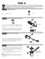
Page 4: ...by lining up the D shape of the Drive Ring with the D shape on the Outdrive NOTE Only a small amount of Clear Diff Grease is needed It is only used to hold the Drive Ring in place Figure 4 IMPORTANT N...

Page 5: ...continuous bead of Clear Diff Grease 172 to the exposed side of the Diff Ring 108 that is already at tached to the Male Outdrive 19 q 2 Carefully place the Diff Pulley 42 over the post on the Outdrive...

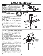
Page 6: ...crew 91 The pen will be used to hold the Diff Nut 27 assembly in the bottom side q 2 Apply a good amount of Clear Diff Grease 172 enouth to cover the Balls completely to the exposed side of the Balls...

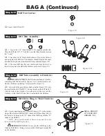
Page 7: ...Assembly to Outdrive Diff Tube Assembly Step A 13 q 1 Apply a small amount of Clear Diff Grease 172 to the outside ridge of the Outdrive Diff Half 87 Attach a Diff Drive Ring 108 to the Outdrive by li...

Page 8: ...nuous bead same as stepA 9 of Clear Diff Grease 172 to the exposed side of the Diff Ring 108 that is already attached to the Male Outdrive 87 q 2 Carefully place the Diff Pulley 42 over the post on th...

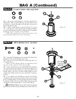
Page 9: ...TE The Thrust Bearing Washers are packaged in a small bag along with the eight 5 64 Thrust Bearing Balls q 3 Grease the Thrust Washer well with MIP RED Thrust Bearing Grease 157 and place the eight 5...

Page 10: ...ng 108 on the Female Outdrive q 3 While holding the Female Outdrive withAllen Wrench inserted carefully assemble it to the Male Outdrive q 4 Make sure that the slot in the Diff Screw is lined up with...

Page 11: ...n the Chassis 46 upside down on your work bench Insert the Belt 77 and pull it through both ends of the Chassis q 2 Pull the Belt out just slightly through the bottom of the Chas sis and insert the St...

Page 12: ...B 3 Front Diff Install Step B 4 Rear Diff Install 129 20 42 62 129 77 46 134 SIDE WITH DIFF NUT 27 118 19 129 118 118 129 87 69 77 42 46 134 87 118 SIDE WITH DIFF NUT 27 Figure 23 Note Use the Steel D...

Page 13: ...e Slipper Hub 103 from the outside large face Slide theTop Shaft 99 through the Bear ing in the Slipper Hub q 2 Place the Spur Gear 71 onto the Slipper Hub and place all six of the Slipper Pucks 156 i...

Page 14: ...ound the Slipper Drive Pulley and Belt Tensioner is in position as shown in Figure 26C secure the Tensioner assembly by threading the 4 40 x 5 16 Button Head Screw with Washer through the Chassis 46 a...

Page 15: ...eering Bushing and into the Bellcranks Figure 28 Figure 29 BAG C 12 q 1 Line up the hex of a Steering Post 97 with the rear hex area on left side of the Chassis 46 Press the Steering Post to the botto...

Page 16: ...o Saver Arm 39 from the front side as indicated in Figure 31 q 3 Plug the servo into the radio system s receiver not included Make sure that there is power to the receiver and turn the transmitter on...

Page 17: ...osition q 2 Place a 4 Washer 151 over each of the four 4 40 x 3 8 Cap Head Screws 131 and attach the Servo Mounts to the servo by threading a Screw with Washer through the servo mounting ears into the...

Page 18: ...o the Ball Stud 80 in the Servo SaverArm 39 and the other to the Ball Stud in the Drag Link 32 as indicated in Figure 35 Step C 6 Servo Install q 1 Install the servo onto the Chassis 46 The pins from...

Page 19: ...s the front of the Chassis 46 Place one Pivot Ball 49 on the rear of each Hinge Pin and insert theArm into the front Inner Pivot Blocks 47 L 48 R Capture the FrontArms by placing the front Main Block...

Page 20: ...he Tower from the same direction as the Cap Head Screws 182 There is a short Thread Cutting Screw included in the Wrench bag This Screw can be used to tap threads in the holes in the Main Chassis Pre...

Page 21: ...q 1 Thread a 3 16 Ballstud 81 through the top side of the left SpindleArm 16 and into a 4 40 x 3 16 Mini Nut 183 as shown in Figure 42A q 2 Install a 3 16 x 3 8 Bearing 116 with the teflon seal facin...

Page 22: ...these Tierod assemblies The two ends of the Turnbuckle are threaded opposite The end closest to the groove next to the square has standard right hand threads the other end has left hand threads This a...

Page 23: ...Rod End 4 onto each end of a 1 375 Tita nium Turnbuckle 141 Tighten both Rod Ends equally until the Tierod is the same length as the assembled Tierod in Figure 47B Make two of these assemblies The tw...

Page 24: ...r Pivots This will ensure you get the correct Pin angle in the Arms q 2 Insert the right rear Arm 11 Arms are labled L and R into the left rear Inner Pivot Block 54 Repeat for the left rear Arm 12 and...

Page 25: ...1 8 Set Screw 136 into the Swaybar Ball and tightening onto the Swaybar q 6 Place the Swaybar against the Shock Tower as shown in Figure 51 and slide it up under the rear Body Mount Capture the Swayb...

Page 26: ...3A Insert the greased CVD Coupling into the large hole in the CVD Axle 113D so that the cross hole in the Coupling can be seen through the slots in the Axle q 2 Place the CVD Bone 113E over the CVDAxl...

Page 27: ...ulder of theAxle stops at the Bearing Slide theAxle Washer 90 over theAxle up against the outside Bearing Secure theAxle and Washer with a 1 16 x 5 16 roll Pin 113F through the cross hole in theAxle T...

Page 28: ...q 1 Place a Foam Thing 185 over the Ball Stud 107 in the left rear Hub Carrier 23 Place a second Foam Thing over the Ball Stud 33 in the rear Shock Tower 58 Assure that the drive end of the CVD Bone i...

Page 29: ...tween the grooves and thread a Shock End 2 all the way onto the Shaft until the threads stop Do this for all four Shock Shafts The front Shock Shafts are the shorter of the four q 3 Place one 0 090 S...

Page 30: ...the way in secure the Cartridge by tightening with pliers or preferrably a 7 16 wrench approximately 1 8 of a turn There should be no air in the Shocks as you move the Shaft 79 in and out If there is...

Page 31: ...onto the Shock Mount Screw q 5 Repeat Steps 1 4 for the right side rear Shock Assembly 184 Step F 6 Rear Shock Install Step F 7 Front Shock Install 129 Figure 67 25 129 184 26 Figure 68 q 1 Position t...

Page 32: ...squeeze the Tire to properly seat it into the grooves of the Wheel Make certain that the Tire Insert is not pinched between the Tire and the Wheel IMPORTANT NOTE Always wear eye protection a mask and...

Page 33: ...gh the Chassis into the two holes in the back of the front Bumper as indicated in Figure 70 q 2 Thread two 4 40 x 3 8 Cap Head Screws 131 through the front Bumper into the front Diff Cover Figure 70 1...

Page 34: ...ex on the Insert with the hex in the bottom of the Chassis The inserts should be installed in the direction shown in Figure 73 q 2 Install the Motor Mount with the motor attached in the groove on the...

Page 35: ...ly residue that may be present on the Chassis or receiver Allow the alcohol to dry before applying the Two sided Tape q 3 Peel the backing off the the Two sided Tape and install the receiver to the le...

Page 36: ...Figure 76B Gear Cover Installation Body Mounting 124 Figure 76A q 1 Locate the Gear Cover 191 and cut the bottom side of it along the trim line as shown in gray in Figure 76B Drill three 1 8 mounting...

Page 37: ...are located q 2 Align the holes in the Rear wing with the Wing Mounts on the rear Shock Tower q 3 Secure the Wing to the Wing Mounts by first placing the Wing on the Mounts followed by a Wing Washer 6...

Page 38: ...ition Some speed controls have a high low setting for the throttle 8 Set transmitter steering trim The steering trim tab on the transmitter should be ad justed so that the car rolls straight when you...

Page 39: ...ding 1 degree front camber will typically increase steering Front Kickup Anti dive is the angle of the front arms in relation to the track surface The kickup is controlled by the pivot blocks that mou...

Page 40: ...in per side stock Adding toe in will create more forward traction and make the car freer on entering a turn This is good for slick surfaces Too much toe in will make the car twitchy and hard to drive...

Page 41: ...540 Steering Bellcranks Servo Saver Mounts XXX S 4 31 RIGHT BELLCRANK A 1540 Steering Bellcranks Servo Saver Mounts XXX S 4 32 DRAG LINK A 1540 Steering Bellcranks Servo Saver Mounts XXX S 4 33 LONG S...

Page 42: ...tanium Nitride Shock Shaft 84 THREADED SHOCK BODY SHORT HRD A 5054 6 Threaded Shock Body Set 85 THREADED SHOCK BODY X LONG HRD A 5056 1 2 Threaded Shock Body Set 86 DIFF TUBE A 3072 Tranny Diff Tube 8...

Page 43: ...E 1 625 N A 140 KINGPIN SCREW A 6235 King Hinge Pin Screws 141 TITANIUM TURNBUCKLE 1 375 N A 142 4 40 X 3 8 BUTTON HEAD A 6229 4 40 x 3 8 Button Head Screws 143 4 40 X 5 16 TRI LOB CAP N A 144 4 40 X...

Page 44: ...SHOCK FLUID A 5224 Silicone Shock Oil 30Wt 2oz 191 GEAR COVER A 4209 Gear Cover Screws 192 BODY WING A 8047 Aurora XXX 4 G Body Wing 193 SLIPPER WRENCH A 3264 Slipper Rebuild Kit XXX 4 194 HINGE PIN...

Reviews: