Where an inline pressure filter is fitted, the element should
be replaced annually. To replace the element, remove the
guard covering the hydraulic valve on the front of the
machine and unscrew the filter canister. Replace the
element, retighten the canister, pressurise the system,
inspect for any leaks from the canister and fit valve guard.
13.10.2 Hose Inspection
IMPORTANT:
Due to ageing, wear, damage and for
other reasons, hydraulic hose assemblies represent a
particular hazard. Therefore, the user has to check
hydraulic hose assemblies prior to their first use and at
regular 3 month intervals.
NOTE:
Subject to the conditions of operation, all
hydraulic hoses have a defined lifespan of up to 8 years.
It is recommended that the hoses are replaced within this
time to minimise risk of failure.
Visual Inspection Hose/Fitting:
Any of the following
conditions require immediate shut down and replacement
of the Hose Assembly:
Fitting slippage on Hose;
Damaged, cracked, cut or abraded cover (any
reinforcement exposed);
Hard, stiff, heat cracked, or charred Hose;
Cracked, damaged, or badly corroded Fittings;
Leaks at Fitting or in Hose;
Kinked, crushed, flattened or twisted Hose;
Blistered, soft, degraded, or loose cover.
Functional Test:
WARNING:
Fluids under pressure can be dangerous
and potentially lethal and, therefore, extreme caution
must be exercised when working with fluids under
pressure and handling the Hoses transporting the fluids.
From time to time, Hose Assemblies will fail if they are not
replaced at proper time intervals. When Hoses fail,
generally the high pressure fluids inside escape in a
stream which may or may not be visible to the operator.
Under no circumstances should you attempt to locate a
leak by “feeling” with your hands or any other part of the
body. High pressure fluids can and will penetrate the skin
and cause severe tissue damage and possibly loss of
limb.
WARNING:
Even seemingly minor hydraulic fluid
injection injuries must be treated immediately by a
doctor with knowledge of the tissue damaging properties
of hydraulic fluid.
Operate the system at maximum operating pressure and
check for possible malfunctions and leaks. Avoid potential
hazardous areas while testing and using the system.
13.11 Electric Controls For Solenoid Valve
NOTE:
Before maintaining any part of the electronic
controls and wires, disconnect the 12v supply. Failure to
do so may result in damage to the electronic circuit
controlling the bed chain speed.
It is recommended that the controls are repaired by a
competent person. Please contact Teagle Machinery
Ltd if repairs are required.
NOTE.
The electric controls require no maintenance and
it is imperative that no part of the system is ever sprayed
with a moisture repelling agent such as WD40.
When the machine is not being used it is recommended
that the control desk is stored safely away from the
machine in a dry location or under the cover provided on
the front of the machine.
The plug on the end of the
machine cable should be kept stored in the bracket
provided to keep it clean and safe from damage.
If problems are experienced with either the hydraulic
system, cable or electric controls, please contact Teagle
Machinery Ltd. for advice as a separate manual is
available to cover troubleshooting and repair. Alternatively
manuals can be viewed on the Teagle Machinery website
by joining the owners club and registering your machine
serial number.
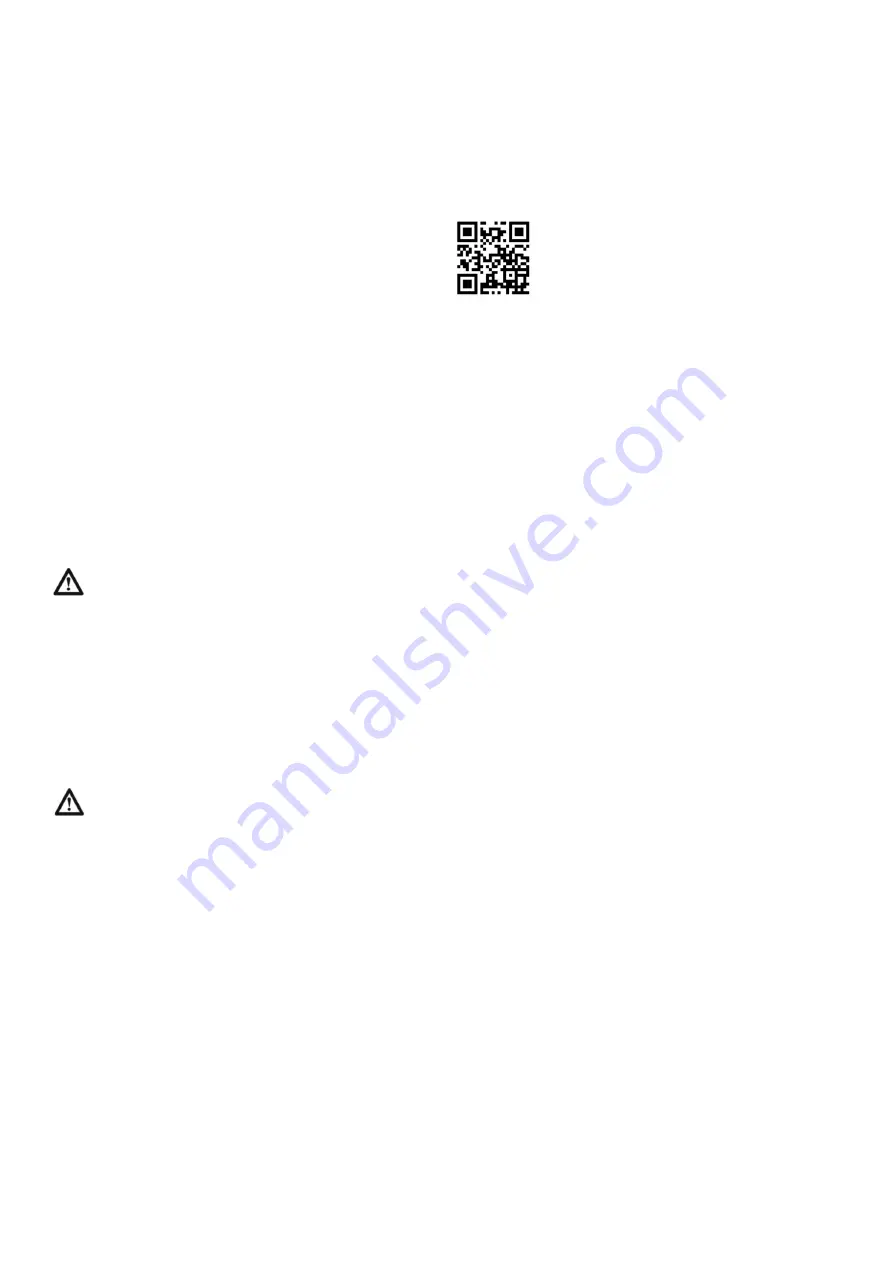
Scan the QR code to take you to the owners
club registration page or go onto the website
www.teagle.co.uk and select the owners
club.
13.12 Slip Clutch
13.12.1 Slip Clutch Maintenance
The condition of the slip clutch should be checked
monthly and before use if the machine has not been used
for a period of time. Moisture can cause the friction discs
to seize onto clutch plates, this results in the driveline of
the machine and the tractor not being protected from
overload.
The clutch should be stripped apart, the friction discs
removed and the friction surfaces of the clutch cleaned.
The clutch pack should then be reassembled to give the
correct torque setting.
Detailed instructions on maintaining your slip clutch can
be viewed on the Teagle Machinery website by joining the
owners club and registering your machine serial number.
13.12.2 Slip Clutch Slips Repeatedly
If the clutch slips repeatedly for no apparent reason there
are a number of things to be check:
Firstly check there is no physical blockage of the
discharge rotor or other mechanical fault in the driveline.
Check that the clutch linings do not show signs of damage
or excessive wear. If so, they should be replaced. When
new they are 3mm (1/8") thick.
Check that the clutch pack is correctly set to give the
correct torque setting.
If the clutch continues to slip it should be adjusted as
follows.
1.
Remove the guard fitted to the rotor gearbox.
2.
Fit the PTO shaft with the slip clutch at the machine
end.
3.
Insert a piece of wood through the discharge chute
and position it such that it prevents the rotor from
turning.
4.
Insert a steel bar through the rear PTO yoke and use a
spring balance to obtain the correct torque setting.
The clutch should just slip at a torque of 1200 Nm (900
lbft)
-
equal to a force of 1000N at 1.2m (225 lb at 4ft)
from the centre of the yoke. Adjust the clutch as
necessary. (The slip clutch is set to the minimum
torque setting when manufactured).
Detailed instructions on maintaining your slip clutch can
be viewed on the Teagle Machinery website by joining the
owners club and registering your machine serial number.
13.13 PTO Shaft
Access to the grease nipples for the PTO shaft joints is
via a hole in the cone.
24
Summary of Contents for Tomahawk 7100
Page 1: ...30417 10100 11 19 30970 10345 31725 11338 10056 3694 TMKBXOP1119A...
Page 38: ...NOTES 35...
Page 39: ...36 NOTES...
Page 40: ......


