Betriebsanleitung
Elektrische Crimpmaschine
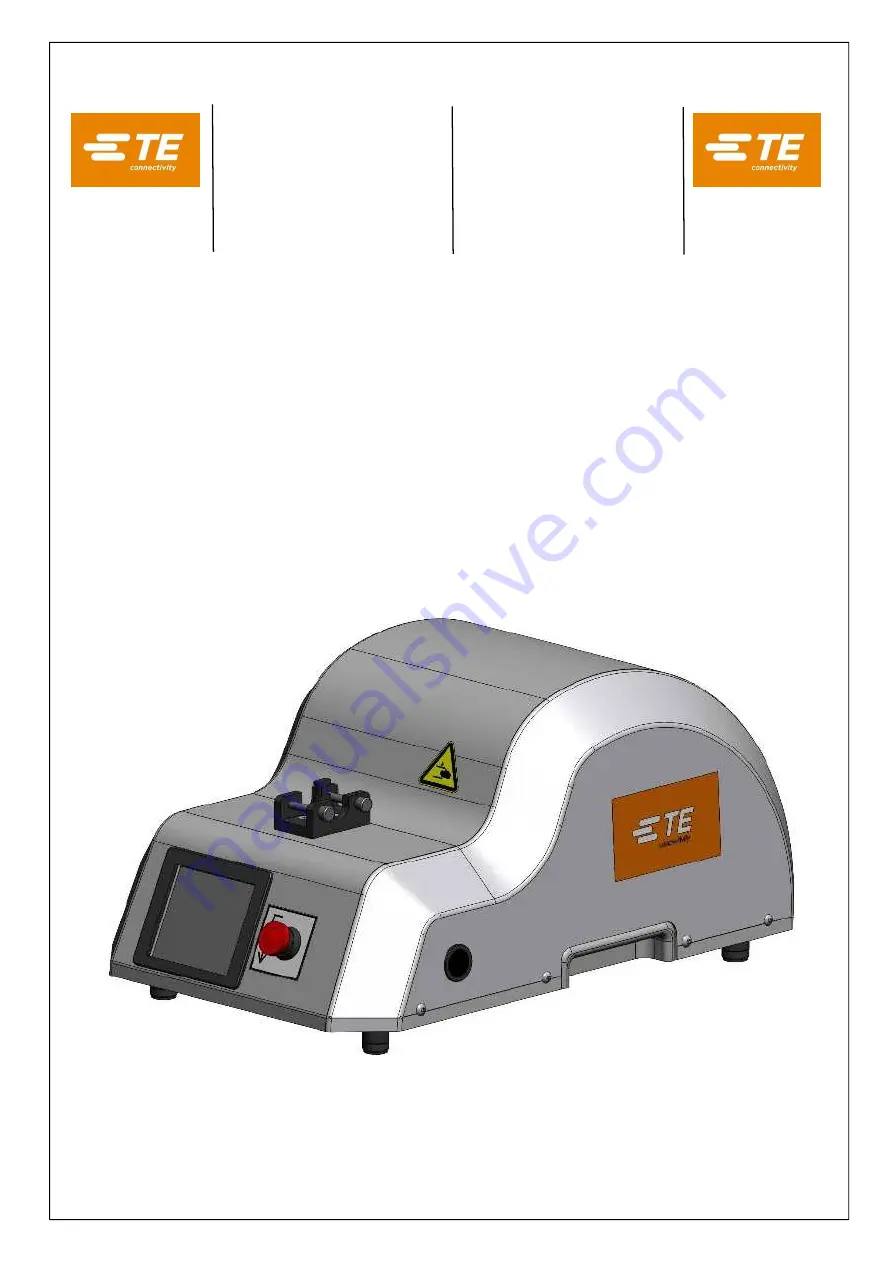
AT-300
TE P/N 539630-2
Operation Manual
Electric Crimping Machine
IS412-94328 / TE P/N 3-744017-7 01MAR2016 REV. B
Page 1: ...Betriebsanleitung Elektrische Crimpmaschine AT 300 TE P N 539630 2 Operation Manual Electric Crimping Machine AT 300 TE P N 539630 2 IS412 94328 TE P N 3 744017 7 01MAR2016 REV B...
Page 2: ...r Anleitung auch auszugsweise gleichg ltig in welcher Form ist ohne ausdr ckliche schriftliche Genehmigung des Herausgebers verboten Gegen ber Darstellung und Angaben in dieser Anleitung sind technisc...
Page 3: ...Seite Page 3 85 Electric Crimping Machine AT 300 IS412 94328 Rev B Deutsche Version Original Version Inhaltsverzeichnis 4 English Version Translation Table of contents 45...
Page 4: ...egrierter St ckz hler 17 4 4 6 Werkzeugaufnahme 17 4 4 7 Fu schalter 18 5 Transport und Aufstellung 19 Transport 19 Aufstellung 19 6 Inbetriebnahme 20 Anschlie en an die Stromversorgung 21 Einsetzen d...
Page 5: ...6 Product Information Center PIC 38 12 Au erbetriebnahme Abbau Demontage 39 13 Lagerung 39 14 Entsorgung 39 15 Ersatzteilliste Stromlaufplan 40 Explosionszeichnung Crimpmaschine 40 St ckliste Crimpmas...
Page 6: ...eck zu verwenden F r Sch den die aus nicht bestimmungsgem er Verwendung entstehen haftet der Hersteller bzw Lieferer nicht das Risiko hierf r tr gt allein der Benutzer RoHS Information Die elektrische...
Page 7: ...Inbetriebnahme Einrichten Betreiben ndern der Einsatzbedingungen und Betriebsweisen Warten und Instandhalten der elektrischen Crimpmaschine AT 300 sind die in der Betriebsanleitung vorgeschriebenen A...
Page 8: ...ist darauf zu achten dass die Maschine gegen Weidereinschalten gesichert ist Beim Ber hren von stromf hrenden Teilen besteht Lebensgefahr Instandhaltungsarbeiten d rfen nur von berechtigten und f r di...
Page 9: ...00 tr gt die Verantwortung dass jede Person die sich mit der Installation oder der Instandhaltung der Maschine befasst anhand der vorliegenden Betriebsanleitung genauestens instruiert worden ist Der B...
Page 10: ...mit Adapter Werkzeugkopf und Gesenken darf nur zur Herstellung von Crimpverbindungen verwendet werden HINWEIS Die elektrische Crimpmaschine AT 300 ist nur unter Verwendung der in Kapitel 7 1 aufgef hr...
Page 11: ...auf Abmessung L nge 800 mm Breite 600 mm H he 570 mm Gesamtgewicht ca 29 kg GEFAHR F r den Transport muss ein ausreichend dimensioniertes Hebezeug verwendet werden Lieferumfang Anzahl Bezeichnung 1 St...
Page 12: ...lay 06 Aufnahme f r Adapter 07 Stecker Fu schalter 08 Schl sselschalter ON OFF Einrichtebetrieb 09 3 poliger Netzsteckeranschluss 10 Sicherung 6 3 A 11 ON OFF Schalter 12 Wechselschalter 115V 230V 13...
Page 13: ...B Abb 4 2 Maschinenidentifikation Typenschild Technische Daten Abmessung L nge 495 mm Breite 320 mm H he 240 mm Gewicht mit Fu schalter ca 17 kg Betriebsspannung 115V 230V Crimpgeschwindigkeit 10 mm s...
Page 14: ...elbsterkl rende Symbole welche teilweise ausgew hlt werden k nnen Symbol Erkl rung Ausw hlbar Ein NEIN Aus NEIN Einrichtebetrieb JA Normalbetrieb 360 1x bet tigen voller Zyklus JA Doppelhub Betrieb St...
Page 15: ...nen Im Display Abb 4 6 erscheint das Symbol Durch Dr cken des Symbols gelangt man in das Einrichtemen siehe Kapitel 7 3 HINWEIS Schl sselstellung I ist nur f r den Einrichtebetrieb zugelassen Nach dem...
Page 16: ...Symbol 4 4 3 R ckstell Taster Sind die Crimpgesenke durch einen Bedienungs oder Handhabungsfehler oder falsches Einlegen eines Crimpkontaktes blockiert wird die elektrische Crimp maschine AT 300 wie f...
Page 17: ...hine AT 300 durch Bet tigen des R ckstell Tasters l sen 4 4 5 Integrierter St ckz hler In dem Display ist der St ckz hler integriert Dieser kann durch Dr cken des Symbols auf 0 zur ckgesetzt werden 4...
Page 18: ...r einsatzbereit HINWEIS Bei voll durchgetretenem Fu schalter verriegelt die Sicherheitssperre Der Pfeil des Entriegelungsschalters steht in der verriegelten Position auf 3 Uhr Der Entriegelungs schalt...
Page 19: ...gt ber keine eigene Lichtquelle Sorgen Sie f r eine ausreichende Beleuchtung des Arbeitsplatzes EN 1837 1999 Kapitel 4 2 Im Allgemeinen muss der Wartungswert der Beleuchtungsst rke mindestens 500 lx...
Page 20: ...an der elektrischen Crimpmaschine AT 300 oder des Adapters inkl Werkzeugkopf oder Gesenke muss die Arbeit unterbrochen und die M ngel behoben werden bevor weiter mit der Maschine gearbeitet werden dar...
Page 21: ...Lieferumfang ist sowohl das Netzkabel EU als auch das Netzkabel US enthalten W hlen Sie das Netzkabel mit dem Netzstecker Ihrer Norm und verbinden Sie dieses mit dem 3 poligem Netzanschluss 4 an der M...
Page 22: ...rischen Anschluss trennen Batterief cher 1 unter der Maschine aufdrehen Batterien 2 x 2 x 1 5 V Babyzellen Typ C mit dem Minuspol nach oben hinter einander einschieben Batterief cher 1 zudrehen Sind f...
Page 23: ...der elektrischen Crimpmaschine AT 300 oder des Adapters inkl Werkzeugkopf oder Gesenke muss die Arbeit unterbrochen und die M ngel behoben werden bevor weiter mit der Maschine gearbeitet werden darf...
Page 24: ...re Adapter HINWEIS Gesenke geh ren nicht zum Lieferumfang Sie k nnen gesondert bestellt werden Beachten Sie die Hinweise zur CE Konformit t in Kapitel 1 2 bzw 2 5 SDE Adapter TE P N 1673663 2 HTV10 Ad...
Page 25: ...diese gedr ckt bis der volle Arbeitszyklus beendet ist Der St el steht jetzt in der untersten Position Abb 7 6 Doppelhub Betrieb Die elektrische Crimpmaschine AT 300 ist werkseitig auf den vollen Arbe...
Page 26: ...HINWEIS Schl sselstellung I ist nur f r den Einrichtebetrieb zugelassen Schl sselstellung I Einrichtebetrieb Die Sicherheitseinrichtung Drucktaste ist ausgeschaltet Das Ger t l sst sich durch den Einr...
Page 27: ...ie wie folgt vor Dr cken Sie das Symbol um den Motor schrittweise langsam vorw rts laufen zu lassen Abb 7 12 Dr cken Sie das Symbol um den Motor schrittweise langsam r ckw rts laufen zu lassen Abb 7 1...
Page 28: ...hender Gefahr den R ckstell Taster sofort Der R ckstell Taster muss vom Bediener jederzeit direkt zug nglich bleiben Er darf nicht verdeckt werden Tragen Sie beim Arbeiten mit der elektrischen Crimpma...
Page 29: ...llteilen der Maschine muss frei gehalten werden Es gilt insbesondere f r den Fu schalter und den R ckstell Taster rastend Bet tigen Sie bei drohender Gefahr den R ckstell Taster sofort Der R ckstell T...
Page 30: ...llen Zyklus betrieben werden Crimpvorgang im vollen Zyklus 1 ffnen Sie die Gesenke indem Sie den Hebel des Adapters nach unten dr cken 2 Halten Sie den Hebel gedr ckt und legen Sie den Crimpkontakt in...
Page 31: ...en Versorgung getrennt wurde WARNUNG Halten Sie die Wartungsintervalle streng ein Instandhaltungsarbeiten d rfen nur von berechtigten und f r diese T tigkeit ausgebildeten Personen ausgef hrt werden I...
Page 32: ...igt werden Grobe Ver schmutzung und Abrieb absaugen 10 1 1 T glich Optische Kontrolle der elektrischen Crimpmaschine AT 300 Gesenke und Werkzeugk pfe sollten vor jedem Gebrauch in dem Profilbereich ge...
Page 33: ...l sselschalters Falls die Schl ssel f r den Schl sselschalter verloren gehen muss der Schl sselschalter 1 ausgewechselt werden Durchf hrung Elektrischen Anschluss trennen Werkzeugaufnahme demontieren...
Page 34: ...er der mit Arbeiten an der Maschine beauftragt ist muss die Betriebsanleitung gelesen und verstanden haben Er muss w hrend der Durchf hrung von Arbeiten an oder mit der Maschine diese Betriebsanleitun...
Page 35: ...n Maschine ist nicht in Endstellung Maschine im vollen Arbeitszyklus neu bet tigen Maschinenst el in unterste Position bringen siehe Kapitel 7 1 Adapter ist nicht in Endstellung Crimpamboss in unterst...
Page 36: ...es Sobald ein Fehler auftritt erscheint ein Fehlercode im Display wie z B in Abb 11 1 Nachfolgend finden Sie die Auflistung der Fehlercodes mit entsprechender Erkl rung Fehlercode Erkl rung Fehlerbehe...
Page 37: ...ung des Motors ist falsch falsche Verdrahtung Maschine an TE zur cksenden 048111000x16 Kurzschluss im Fu schalterkabel Maschine an TE zur cksenden 048111000x17 R ckstell Taster ausgel st R ckstelltast...
Page 38: ...y GmbH a TE Connectivity Ltd company Schenck Technologie und Industriepark Landwehrstr 55 Geb ude 83 DE 64293 Darmstadt TE AT Kundendienst Hotline 49 0 6151 607 1518 E Mail TEFE1 te com EMEA Field Ser...
Page 39: ...eine lose Kleidung losen Schmuck oder lange offene Haare welche sich in dem Mechanismus verfangen k nnen Tragen Sie beim Transport und beim Abbau der elektrischen Crimpmaschine AT 300 geeignete Sicher...
Page 40: ...Seite Page 40 85 Electric Crimping Machine AT 300 IS412 94328 Rev B 15 Ersatzteilliste Stromlaufplan Explosionszeichnung Crimpmaschine Abb 15 1...
Page 41: ...15 7 1 523648 5 HEX SOCKET SCREW M4X18 16 3 1 523648 6 SOCKET 12 0 6 2X8 0 17 3 1 523648 7 HEX SOCKET COUNTERSUNK HEAD SCREW M6X35 18 1 1 523648 8 SERRATED WASHER A 6 4 19 1 1 523648 9 HEX NUT B M6 2...
Page 42: ...AD SCREW M5X20 55 1 5 523648 5 BRIDGE 56 1 5 523648 6 DU SOCKET MB 0810 57 2 5 523648 7 HEX SOCKET SCREW M2X10 58 1 5 523648 8 SEGMENT BOARD HOLDING PLATE 59 6 5 523648 9 DISK A3 2 60 4 6 523648 0 HEX...
Page 43: ...et sind sind oder stehen in Verbindung mit sicherheitsrelevanten Bauteilen der elektrischen Crimpmaschine AT 300 Die Montage sollte durch TE erfolgen Beim Austausch von sicherheitsrelevanten Bauteilen...
Page 44: ...1 X 9 523648 5 RELEASE BUTTON 16 1 9 523648 6 SWITCHING ELEMENT RELEASE BUTTON 17 1 X 9 523648 7 DISPLAY FT800 INCL FRAME Alle Ersatzteile die nicht mit einem X gekennzeichnet sind sind oder stehen i...
Page 45: ...tch 55 4 4 3 Release Button 56 4 4 4 Battery Compartment 57 4 4 5 Integrated Piece Counter 57 4 4 6 Tool Holding Device 57 4 4 7 Foot Pedal 58 5 Transport and Installation 59 5 1 Transport 59 5 2 Inst...
Page 46: ...of Error Prompts 76 11 3 Product Information Center PIC 78 12 Removal from Service Demounting Disassembly 79 13 Storage 79 14 Disposal 79 15 Exploded View Drawing Spare Part List Circuit Diagram 80 1...
Page 47: ...damages which may result due to the machine being used for a purpose other than that for which it was intended This is done entirely at the user s own risk RoHS Information The electric Crimping Machi...
Page 48: ...se and the mode of operation or carrying out maintenance and service jobs it is important to observe the procedures for switching off the machine described in the operation instruction Please observe...
Page 49: ...specially trained staff Due to the risk of hand or finger injury never try to reach into the electric Crimping Machine AT 300 before having assured that the machine is disconnected from the power supp...
Page 50: ...machine To assure full familiarization with the system the training must be conducted in the native language of the operators involved Staff qualifications required in conjunction with the use of the...
Page 51: ...ived all components against the packing slip declaration of conformity and operation manual We recommend that you retain the packing for further dispatch and for storage Dimension Length 800 mm 31 5 W...
Page 52: ...06 Holding devise for the adapter 07 Socket for foot pedal 08 Key switch ON OFF Supervisor Mode 09 3 pole main plug connection 10 Fuse 6 3 A 11 ON OFF switch 12 Voltage selector 115V 230V 13 Identific...
Page 53: ...ication Identification Plate 4 3 Technical Data Dimension Length 495 mm 19 5 Width 320 mm 12 6 Height 240 mm 9 5 Weight with foot pedal approx 17 kg 37 lbs Operational Voltage 115V 230V Crimp speed 10...
Page 54: ...ively by self explanatory icons which can partly be selected Symbol Explanation Selectable On NO Off NO Set up Mode YES Normal Operation 360 press once complete cycle YES Double Step Mode Step 01 10 p...
Page 55: ...splay shows the following symbol Fig 4 6 Touch the icon to enter the set up menu see chapter 7 3 INFORMATION Key position I is only allowed to be used by supervisors or authorized personnel After the...
Page 56: ...4 4 3 Release Button In case of jammed jaws caused by operation or handling errors or wrongly placed terminals the electrical crimping machine AT 300 can be opened as follows Press the release button...
Page 57: ...hine AT 300 can be opened by pressing the release button 4 4 5 Integrated Piece Counter The piece counter is integrated within the display By touching the icon the piece counter can be reset to 0 4 4...
Page 58: ...hine is ready for operation again INFORMATION Over pressing the foot pedal will trip the safety lock It will rotate to the 3 o clock position and the machine will not function To reset the safety lock...
Page 59: ...4 4 2004 Table A 1 The crimping machine has no own light source Assure appropriate illumination of the working place EN 1837 1999 chapter 4 2 The general value of illumination has to be 500 lx Place t...
Page 60: ...covered When working with the electric Crimping Machine AT 300 do not wear loose clothing jewellery or long loose hair that can get caught in the mechanism Work with caution In cases of a malfunction...
Page 61: ...ght Fig 6 1 6 2 A power cable EU as well as a power cable US are included within the scope of delivery Choose the power cable with a main plug of your norm and connect it with the 3 pole main plug con...
Page 62: ...attery compartments 1 under the electric Crimping Machine AT 300 to open them Insert the batteries 2 x 2 x 1 5 V Baby Cells Type C one after another with the negative pole pointing to the top Close ba...
Page 63: ...d When working with the electric Crimping Machine AT 300 do not wear loose clothing jewellery or long loose hair that can get caught in the mechanism Work with caution In cases of a malfunction of the...
Page 64: ...ailable Adapters INFORMATION Die sets are not included in delivery and have to be ordered separately Pay attention to the CE information in chapter 1 2 and 2 4 SDE Adapter TE P N 1673663 2 HTV10 Adapt...
Page 65: ...ition II Pay attention to the fact that the machine is set for the full working cycle Fig 7 5 If this is not the case touch icon After step 10 the following icon appears The machine is now in the full...
Page 66: ...parate steps first step Fig 7 8 for holding the inserted contact second step Fig 7 9 for crimping and moving back into the final position The ram position can be adjusted to the respective contact mat...
Page 67: ...r place on the display the display has to be calibrated Please proceed as follows Touch icon to calibrate the display Follow the instructions on the display 7 4 2 Manual Motor Movement To move the ele...
Page 68: ...ping Machine AT 300 especially the foot pedal and the release button In the case of imminent danger immediately press the release button The release button must be within the direct reach of the opera...
Page 69: ...is only allowed to be used with mounted adapter with tool head or with die set Assure free access to the operating elements of the electric Crimping Machine AT 300 especially the foot pedal and the r...
Page 70: ...pen the dies by depressing the lever of the adapter 2 Keep it depressed and insert the crimp contact in the die profile or locator Please pay attention to the correct profile assignment and to the cor...
Page 71: ...staff The housing and the covers in particular may only be removed by specially trained staff Do not operate the electric Crimping Machine AT 300 before having read and understood all operating instru...
Page 72: ...cked for any damage before every use Lightly lubricate the profiles 10 1 2 Every 25 000 Cycles Lubricate the crimping ram with the Blaser Swiss Lube Art No 00492 01 EP Universal Grease Grease the driv...
Page 73: ...hine AT 300 on a flat surface and assure the stability of the machine Ensure that the table or bench is stable enough to support the machine in normal use If the keys for the key switch get lost the k...
Page 74: ...ping Machine AT 300 Every machine operator must have read and understood this operating instruction The safety instructions warnings and precautions contained in the individual chapters must be strict...
Page 75: ...he adapter does not engage correctly into the ram of the machine See chapter 8 Adapter Tool head does not open Move adapter tool head backwards in set up mode chapter 7 4 2 Remove adapter tool head Cl...
Page 76: ...8111000x04 Battery empty Insert new batteries 048111000x05 Fuse 1 on control board has tripped Send the machine back to TE 048111000x06 Fuse 2 on control board has tripped Send the machine back to TE...
Page 77: ...ard x 048111000x20 Temperature of the machine too high Stop working with the machine and let it cool down 048111000x21 Error prompt not assigned Send the machine back to TE 048111000x22 Unknown error...
Page 78: ...dendienst Hotline 49 0 6151 607 1518 E Mail TEFE1 te com EMEA Field Service Hotline TEFE2 te com EMEA Hand Tool Repair TEFE3 te com EMEA Wear Spare Parts TEFE4 te com EMEA Field Service Admin Short Te...
Page 79: ...th the electric Crimping Machine AT 300 do not wear loose clothing jewellery or long loose hair that can get caught in the mechanism During transport and demounting of the machine wear suitable safety...
Page 80: ...Seite Page 80 85 Electric Crimping Machine AT 300 IS412 94328 Rev B 15 Exploded View Drawing Spare Part List Circuit Diagram 15 1 Exploded View Drawing Fig 15 1...
Page 81: ...LINDER PIN 4M6X18 15 7 1 523648 5 HEX SOCKET SCREW M4X18 16 3 1 523648 6 SOCKET 12 0 6 2X8 0 17 3 1 523648 7 HEX SOCKET COUNTERSUNK HEAD SCREW M6X35 18 1 1 523648 8 SERRATED WASHER A 6 4 19 1 1 523648...
Page 82: ...DING DEVICE COMPLETE 54 4 x 5 523648 4 HEX SOCKET COUNTERSUNK HEAD SCREW M5X20 55 1 5 523648 5 BRIDGE 56 1 5 523648 6 DU SOCKET MB 0810 57 2 5 523648 7 HEX SOCKET SCREW M2X10 58 1 5 523648 8 SEGMENT B...
Page 83: ...ON PALTE 82 4 BLIND RIVET NUT 2 4X8 All spare parts which are not marked with an X are safety related parts or in connection with safety related parts of the machine This repair assembly should be mad...
Page 84: ...Seite Page 84 85 Electric Crimping Machine AT 300 IS412 94328 Rev B 15 3 Circuit Diagram Fig 15 2...
Page 85: ...IN PRESSURE BUTTON ROUND 15 1 X 9 523648 5 RELEASE BUTTON 16 1 9 523648 6 SWITCHING ELEMENT RELEASE BUTTON 17 1 X 9 523648 7 DISPLAY FT800 INCL FRAME All spare parts which are not marked with an X are...