41/ 42
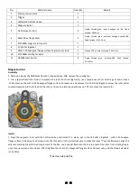
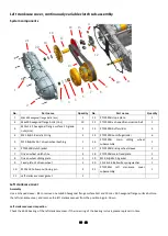
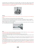
To tap symmetrically on the reinforcement hole of the right crankcase or the process boss to separate the left and right
crankcases evenly, and take out the crankshaft and the right crankcase together. And take out the positioning pin together
(note:
do not hit the joint surface of the crankcase or other assembly joint surfaces; the right crankcase and the crankshaft belong to
interference fit, and there is no need Assembly the two
).
Inspection
1.
Thoroughly clean the crankcase with a mild solvent before inspection, and remove the residual glue on the assembly joint
surface;
2. Check the crankshaft gear, tooth surface and spline for abnormal wear and damage;
3. Check whether there is any abnormal wear and deformation on the surface of the crankshaft. If so, replace the crankshaft;
4. Turn the outer ring of the crankshaft bearing by hand to check whether the bearing rotates smoothly, whether there is
stagnation or pitting, and if so, replace the crankshaft;
5. Check the crankcase. If any functional damage such as cracks or serious scratches on the joint surface is found in the crankcase,
the corresponding crankcase should be replaced.
Install
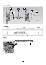
Loctite 5900 plane sealant
evenly and continuously on the joint surface of the left crankcase
(note: if there is uneven glue
application or even broken glue, the glue should be manually replenished
);
2. Put two φ 10×14 hollow positioning pins into the cor
responding positioning pin holes of the left box;
3. Spray an appropriate amount of engine oil on the outer ring of the left crankshaft bearing and the joint surface of the left
crankcase bearing.
4. Align the crankshaft in the right crankcase with the bearing hole of the left crankcase, align the positioning pin hole on the
joint surface of the right case with the positioning pin and install in place; (note: pay attention to protect the
connecting rod to
prevent scratches
);
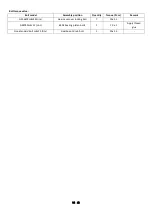
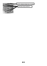
5. Take 8 m6×60 hexagonal flange bolts and 3 m6×105 hexagonal flange surface 9.8 grade bolts, put them into the corresponding
holes in the right box, and use the air batch or t-shaped sleeve-8 from the positioning pin first. # pretighten evenly across the
corners, tighten again, and then use a fixed torque wrench to correct the torque;
(note: the pretightening force is 5±1N.m, and
the correcting torque is 12±1.5N.m. After closing the box, push the connecting rod by hand, and the crankshaft should rotate
smoothly. Stuck
).


