14/ 42
Install
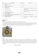
1. As shown in the figure, install the valve (apply oil), valve spring seat, valve stem diameter oil seal (press in place aft
er
installation), valve spring, valve spring retainer, and valve lock clip (install with valve installation tool) in sequence (
note: remove
dust and foreign matter from the valve seat surface and cylinder head seat surface. When installing the valve spring, the
sparse ring faces upward and the dense ring faces downward
).
2. Install the camshaft (O-ring
needs to be installed), the intake rocker arm sub
-assembly, the exhaust rocker arm sub-assembly,
and the intake and exhaust rocker arm shaft in order (rotate the rocker arm shaft so that the slot is in a horizontal positio
n).
(note: O-rings cannot be missed on the camshaft)
3. As shown in the figure, install the camshaft bearing pressure plate, apply an appropriate amount of thread fastening glue on
the surface of 1 m6x10 and 2 m5x15 bolts, after screwing in, pre-tighten and set the torque, the torque is: m6 bolt torque 10±1n.
M , m5 bolt torque 7±1N.m .
Valve clearance
1. As shown in the figure, adjust the valve clearance: align the camshaft groove point with the scale line of the camshaft bearing
pressure plate, insert the feeler gauge between the valve adjustment bolt and the end face of the valve stem, pull the feeler
gauge by hand, and take out the plug after the clearance is qualified. Take a no. 8 torx wrench and put it on the lock nut on the
valve clearance adjustment screw, fix the adjustment screw with a special t-type wrench, and then tighten the nut with a torx
Valve
Valve spring seat
Valve rod diameter oil seal
Valve spring retainer
valve spring
Sparse circles face up, dense circles
face down
apply oil
Valve lock


