32/ 42
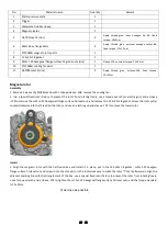
bushing with the other hand to align the inner hole of the driving wheel bushing with the crankshaft. Then the slope plate, the
centrifugal roller, the main sliding wheel sub-components, and the driving wheel bushing are combined and assembled on the
crankshaft as a whole and withstand the
φ 16 × φ 30 × 9
bushing.
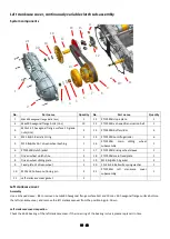
3. Pick up the combined driven wheel and v-shaped transmission belt as a whole, make the clutch outer cover of the driven
wheel face the outside, align the inner hole of the center of the driven wheel with the drive shaft, and then push the driven
wheel inward and install it in place (the drive shaft is used for a section of the optical axis of the φ12.8×φ25×16.7 driven
wheel
bush is exposed).
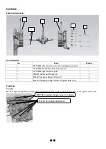
4. Put the side of the main fixed disk with the wind blades facing outward, align the spline hole in the middle with the spline on
the crankshaft, and then assemble it on the crankshaft, and assemble it in place.
Put
the φ12.2×φ29×2.5 washer and 12×24×2.6 butterfly spring washer on the crankshaft in turn, and then screw the m12×1.25
hexagonal flange surface 10-grade nut on the crankshaft thread.
5. Point the stepped end of the φ12.8×φ25×16.7 driven wheel bushing to the driven wheel, and install it on the exposed sectio
n
of the optical shaft of the drive shaft. Then screw on the m12×1.25 hexagon flange face 10 grade nut on the thread of the drive
shaft. (
note: if there is no grease in the groove of the inner ring of the driven wheel bushing, add high-temperature resistant
grease. Do not miss the installation of the 2 O-rings. When screwing the nut, if there is grease on the thread, it needs to be
wiped clean.
)
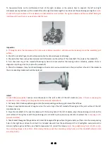
6. Same as the first step of disassembly, use a special fixture to clamp the main fixed plate and the clutch cover of the driven
wheel so that they cannot rotate free
ly, and use a torque wrench (or air batch) and a 17# sleeve to tighten m12×1.25× clockwise
35 hex flange bolts ,fixed torque 50±4N.m.


