


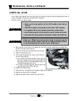


Maintenance, Service, and Repair
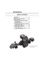
Transmission
Page 4
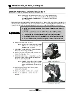
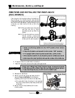
MOTOR REMOVAL AND INSTALLATION
NOTE: Some applications will require removing the drive assembly from
the vehicle to remove the motor. Refer to
Removing and
Installing the Drive Assembly
for information on removing the
drive assembly.
Some vehicles are equipped with an automatic electric brake. The automatic electric brake is sandwiched
between the drive motor and the gear case. The electric brake is retained by the drive motor mounting
screws. Once the motor is removed the electric brake will no longer be retained by any hardware.
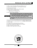
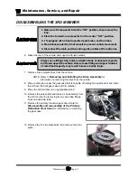
1. Make sure the key-switch is in the “OFF” position, then remove
the key.
2. Place the forward-reverse switch in the center “OFF” position.
3. If equipped with a hand operated park brake, set the brake.
4. Place blocks under the front wheels to prevent vehicle movement.
5. Disconnect the main positive and negative cables at the batteries.
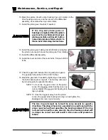
6. Remove the wires from the motor.
NOTE: Label the motor wires with the number
of the motor terminal before they are
removed from the motor.
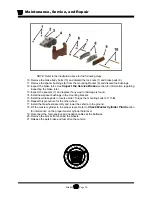
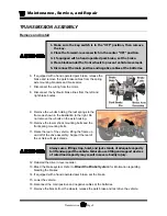
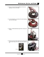
7. If equipped, remove the motor support bracket u-
bolt (only used on larger motors).
8. Remove the motor mounting bolts and slide the
motor off of the input shaft.
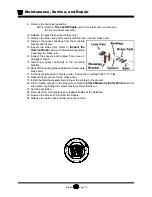
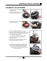
9. Install the motor in reverse order. Make sure that
the motor coupler o-ring is properly installed on
the transmission input shaft.
NOTE: Apply a light coating of part number
94-421-34 moly paste grease to the
splines on the transmission input shaft
only.
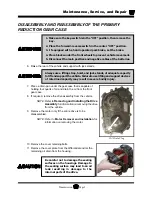
10. Reconnect the main positive and negative
cables at the batteries.
11. Remove the blocks from behind the wheels.
12. Release the park brake and test drive the
vehicle.
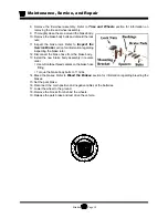
Transmission input shaft
Support bracket u-bolt
Summary of Contents for B0-248-48AC
Page 2: ......
Page 70: ...Maintenance Service and Repair Steering Page 22 Exploded View of Steering Gear...
Page 88: ...TAYLOR DUNN...
Page 114: ...TAYLOR DUNN...
Page 120: ...TAYLOR DUNN...
Page 132: ...TAYLOR DUNN...
Page 134: ...TAYLOR DUNN...
Page 164: ...Illustrated Parts Parts Page 2 Front Axle...
Page 166: ...Illustrated Parts Parts Page 4 Steering Knuckle...
Page 168: ...Illustrated Parts Parts Page 6 Steering Linkage...
Page 174: ...Illustrated Parts Parts Page 12 Rear Suspension View from rear...
Page 176: ...Illustrated Parts Parts Page 14 Transmission Gear Case...
Page 180: ...Illustrated Parts Parts Page 18 Rear Brakes Front Brakes...
Page 182: ...Illustrated Parts Parts Page 20 Brake Lines Master Cylinder...
Page 184: ...Illustrated Parts Parts Page 22 Motor...
Page 186: ...Illustrated Parts Parts Page 24 Motor Mount Apply 94 421 34 grease to inside of motor coupler...
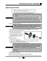
Page 188: ...Illustrated Parts Parts Page 26 Wheels and Tires Ref wheel hub 1 2 5 assembly 4 3 6 7 8 9 10...
Page 196: ...Illustrated Parts Parts Page 34 Lighting Stobe Light 4 1 2 3 5 6 7...
Page 206: ...Illustrated Parts Parts Page 44 Seat Cushions and Deck...
Page 208: ...Illustrated Parts Parts Page 46 Mirrors 92 202 00 Assembly Miscellaneous Frame Components...
Page 210: ...Illustrated Parts Parts Page 48 Decals...
Page 212: ...Illustrated Parts Parts Page 50 Cab Options Steel Cab Fiberglass cab...
Page 218: ...Illustrated Parts Parts Page 56 Hydraulic Dump Body Option...
Page 220: ...Illustrated Parts Parts Page 58 Rear Cargo Box 1 2 3 4 5 6 5 Top Covers...
Page 222: ...Illustrated Parts Parts Page 60 Hitches...
Page 224: ...TAYLOR DUNN...


