SAFETY RULES AND OPERATING INSTRUCTIONS
Safety Rules
Page 12
Model # B 2-48 equipped with 18:1 drive ratio
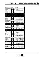
Aceleration Parameters (normal mode)
Function
Value
Unit
Description
FwdAS LS
3.5
S
Time to accelerate to ~15% of full
speed
FwdAc HS
4.0
S
Time to accelerate to full speed
RevAc LS
10.0
S
Time to accelerate to from FwdAC LS
to full
RevAc HS
8.0
S
Time to accelerate to full speed
Aceleration Parameters (low speed mode)
FwdAS LS
4.0
S
Time to accelerate to ~15% of full
speed
FwdAc HS
5.5
S
Time to accelerate to full speed
RevAc LS
10.0
S
Time to accelerate to from FwdAC LS
to full
RevAc HS
10.0
S
Time to accelerate to full speed
Deceleration Settings
Brake Multplier
40
%
Brake regen multiplier is activated by
the brake switch
Normal Decl HS
9.0
S
Time to decelerate to 0 when above
20% of full speed
Normal Decl LS
12.0
S
Time to decelerate when below 20%
of full speed
Tow Decl HS
8.5
S
Time to decelerate to 0 when above
20% of full speed
Tow Decl LS
8.0
S
Time to decelerate when below 20%
of full speed
Maintenance Meter Function
Service Timer
0*
H
Refer to Maintenance Meter
supplementary manual
Speed Limits
Max (see warning)
6,250
RPM Governed speed (see formula)
Tow (optional)
62
%
Percentage of Max speed when Tow
Switch is ON
Rev
45
%
Percentage of Max speed when in
reverse
Low Batt
40
%
Percentage of Max speed when low
battery warning is ON
Service Due
20*
%
Percentage of Max speed when
service is due. See maintenance Meter
Function
Batery Characteristics
Full Volts
2.165
V
Battery must exceed this voltage to be
considered fully charged
Empty Volts
1.730
V
Voltage of a fully discharged battery
BDI Level for Batt Spd
15
%
Low battery warning is ON when
battery is discharged below this level
BDI Reset %
80
%
Battery must be discharged below this
value before the BDI will be allowed
to reset
Reset Volts
2.10
V
Battery voltage must be above this
value to reset the BDI. Modified by
the ‘BDI Reset %’ above)
Discharge Time
60
M
Estimated battery discharge rate
Miscellaneous
SRO Min Speed
3,000
RPM
Motor must be below this RPM to
change directions with the throttle
pedal depressed
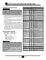
Adjustable Controller Parameters
A limited number of controller parameters can be
adjusted by your dealer. The values of these parameters
will vary depending on the vehicle model and/or
configuration.
A list of the adjustable parameters and their function is
listed on the following pages along with their typical
default factory settings.
Default factory settings are subject to change without
notice. It is highly recommended that you record current
settings in the controller before making any adjustments.
* - The Maintenance Meter Function is optional. When
equipped, the Maintenance Meter Function will notify
the operator when a scheculed maintenance is due.
Refer to the supplementary Maintenance Meter manual
for more information.
Speed Calculation Formulas:
RPM = (20172 / T
d
) * (MPH / 60) * R
RPM = (31837 / T
d
) * (KPH / 60) * R
Where:
RPM
= motor RPM
T
d
= Tire diameter (inches or cm)
MPH
= Miles Per Hour
KPH
= Kilometers per hour
R
= Rear axle ratio
Improper programming may cause unexpected
operation of the vehicle and/or damage the
electrical components. This could result in
severe bodily injury and/or property damage
Do not increase the governed speed RPM
beyond the maximum recommended speed of
the vehicle. Exceeding the maximum
recommended speed of the vehicle may result
in loss of control and severe bodily injury or
property damage.
Refer to Vehicle Specifications for vehicle
speed limit.
Summary of Contents for B0-248-48AC
Page 2: ......
Page 70: ...Maintenance Service and Repair Steering Page 22 Exploded View of Steering Gear...
Page 88: ...TAYLOR DUNN...
Page 114: ...TAYLOR DUNN...
Page 120: ...TAYLOR DUNN...
Page 132: ...TAYLOR DUNN...
Page 134: ...TAYLOR DUNN...
Page 164: ...Illustrated Parts Parts Page 2 Front Axle...
Page 166: ...Illustrated Parts Parts Page 4 Steering Knuckle...
Page 168: ...Illustrated Parts Parts Page 6 Steering Linkage...
Page 174: ...Illustrated Parts Parts Page 12 Rear Suspension View from rear...
Page 176: ...Illustrated Parts Parts Page 14 Transmission Gear Case...
Page 180: ...Illustrated Parts Parts Page 18 Rear Brakes Front Brakes...
Page 182: ...Illustrated Parts Parts Page 20 Brake Lines Master Cylinder...
Page 184: ...Illustrated Parts Parts Page 22 Motor...
Page 186: ...Illustrated Parts Parts Page 24 Motor Mount Apply 94 421 34 grease to inside of motor coupler...
Page 188: ...Illustrated Parts Parts Page 26 Wheels and Tires Ref wheel hub 1 2 5 assembly 4 3 6 7 8 9 10...
Page 196: ...Illustrated Parts Parts Page 34 Lighting Stobe Light 4 1 2 3 5 6 7...
Page 206: ...Illustrated Parts Parts Page 44 Seat Cushions and Deck...
Page 208: ...Illustrated Parts Parts Page 46 Mirrors 92 202 00 Assembly Miscellaneous Frame Components...
Page 210: ...Illustrated Parts Parts Page 48 Decals...
Page 212: ...Illustrated Parts Parts Page 50 Cab Options Steel Cab Fiberglass cab...
Page 218: ...Illustrated Parts Parts Page 56 Hydraulic Dump Body Option...
Page 220: ...Illustrated Parts Parts Page 58 Rear Cargo Box 1 2 3 4 5 6 5 Top Covers...
Page 222: ...Illustrated Parts Parts Page 60 Hitches...
Page 224: ...TAYLOR DUNN...


