


Maintenance, Service, and Repair
Steering
Page 20
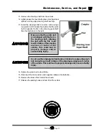
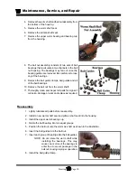
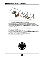
4. Remove the worm shaft and ball nut assembly from
the bottom of the housing.
5. Remove the worm shaft seal.
6. Remove the pitman shaft seal.
7. Remove the upper worm bearing and bearing cup
from the housing.
8. The ball nut assembly consists of two sets of ball
bearings that recirculate in two channels in the ball
nut housing. The bearings may fall out once the
bearing guides are removed. Be careful not to lose
any of the bearings.
9. Remove the ball guide clamps, ball guides and all
of the ball bearings.
10. Remove the ball nut from the worm shaft.
11. Thoroughly clean and inspect all parts for signs of
corrosion, damage or wear and replace as required.
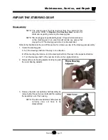
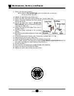
Reassembly
1. Lightly lubricate all parts before reassembly.
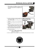
2. Install a new worm shaft seal and pitman shaft seal into the housing.
3. Install the upper worm bearing cup.
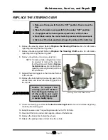
4. Divide the ball bearing into two equal groups.
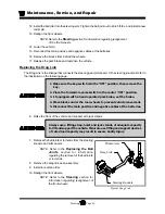
5. Position the ball nut onto the worm as shaft as shown in the illustration.
6. Insert the ball guides into the ball nut.
7. Insert each group of bearings into the ball guides.
NOTE: Do not rotate the worm shaft while
installing the bearings. This may
cause one or more of the bearings to
enter the crossover passage in the
ball nut, causing improper operation.
8. Install the ball guide clamp.
Summary of Contents for B0-248-48AC
Page 2: ......
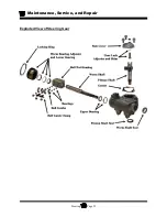
Page 70: ...Maintenance Service and Repair Steering Page 22 Exploded View of Steering Gear...
Page 88: ...TAYLOR DUNN...
Page 114: ...TAYLOR DUNN...
Page 120: ...TAYLOR DUNN...
Page 132: ...TAYLOR DUNN...
Page 134: ...TAYLOR DUNN...
Page 164: ...Illustrated Parts Parts Page 2 Front Axle...
Page 166: ...Illustrated Parts Parts Page 4 Steering Knuckle...
Page 168: ...Illustrated Parts Parts Page 6 Steering Linkage...
Page 174: ...Illustrated Parts Parts Page 12 Rear Suspension View from rear...
Page 176: ...Illustrated Parts Parts Page 14 Transmission Gear Case...
Page 180: ...Illustrated Parts Parts Page 18 Rear Brakes Front Brakes...
Page 182: ...Illustrated Parts Parts Page 20 Brake Lines Master Cylinder...
Page 184: ...Illustrated Parts Parts Page 22 Motor...
Page 186: ...Illustrated Parts Parts Page 24 Motor Mount Apply 94 421 34 grease to inside of motor coupler...
Page 188: ...Illustrated Parts Parts Page 26 Wheels and Tires Ref wheel hub 1 2 5 assembly 4 3 6 7 8 9 10...
Page 196: ...Illustrated Parts Parts Page 34 Lighting Stobe Light 4 1 2 3 5 6 7...
Page 206: ...Illustrated Parts Parts Page 44 Seat Cushions and Deck...
Page 208: ...Illustrated Parts Parts Page 46 Mirrors 92 202 00 Assembly Miscellaneous Frame Components...
Page 210: ...Illustrated Parts Parts Page 48 Decals...
Page 212: ...Illustrated Parts Parts Page 50 Cab Options Steel Cab Fiberglass cab...
Page 218: ...Illustrated Parts Parts Page 56 Hydraulic Dump Body Option...
Page 220: ...Illustrated Parts Parts Page 58 Rear Cargo Box 1 2 3 4 5 6 5 Top Covers...
Page 222: ...Illustrated Parts Parts Page 60 Hitches...
Page 224: ...TAYLOR DUNN...


