background image

Chapter 2  Installing the Tape Drive

Installing the Internal SCSI Tape Drive

DLT-V4 Product Manual

19

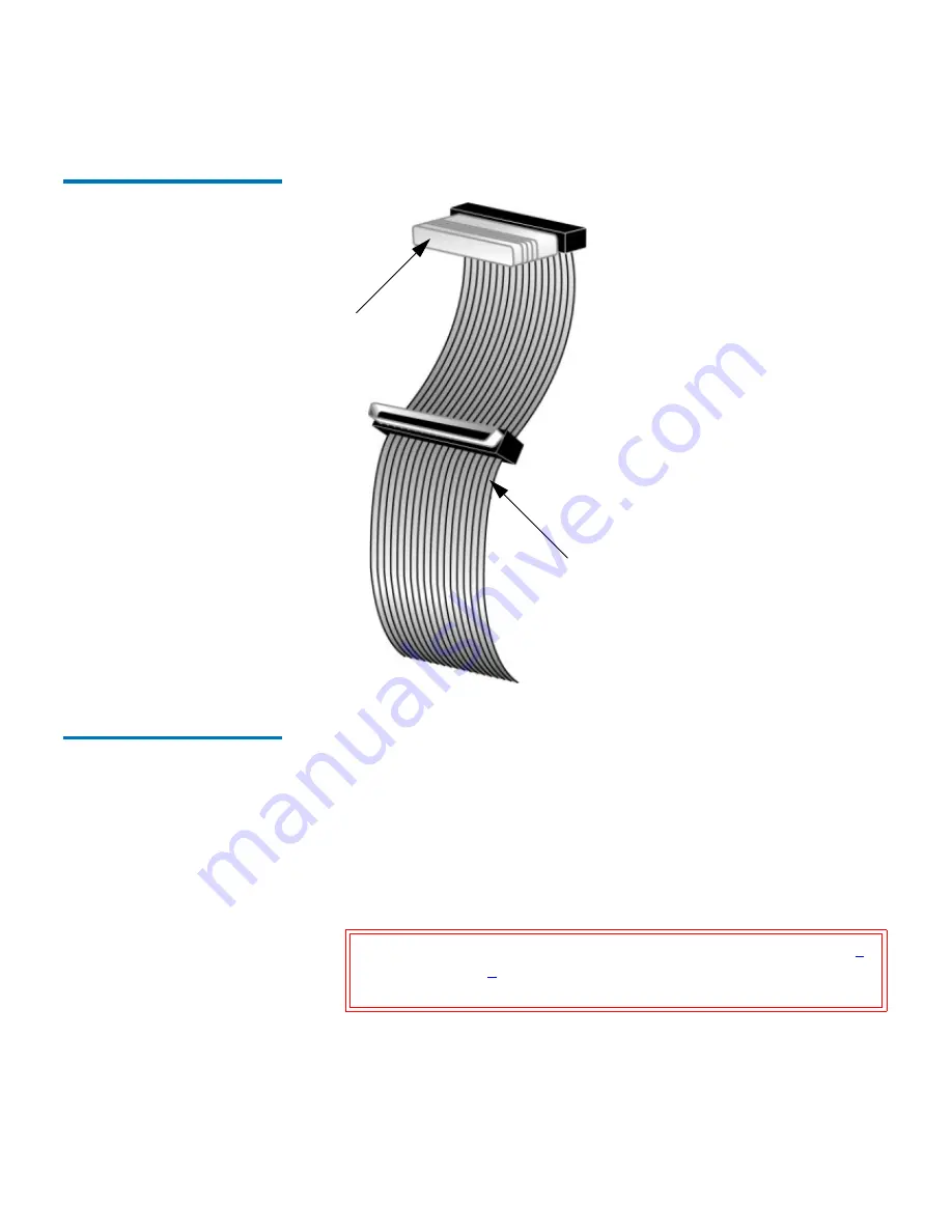
Figure 8  SCSI Cable with Built-
in Terminator

Installing the Internal SCSI 
Tape Drive

2

In the final installation stage, you install the tape drive in the server or 

workstation and connect the SCSI and power cables.
To install the tape drive, follow these steps:

1

Shut down the operating system and power off the server or 

workstation.

2

Power off all peripheral devices, such as printers and other SCSI 

devices.

3

Remove the cover from the server or workstation as described in the 

server or workstation’s documentation.

Caution:

Do not go to step 3 

until you have completed steps 

1


and 

2

. Failure to follow these instructions may result 

in damage to the tape drive or other devices.

Terminator

SCSI cable
(supplied with
host adapter)

Summary of Contents for DLT-V4

Page 1: ...DLT V4 TAPE DRIVE PRODUCT MANUAL...

Page 2: ...ur right to copy this document is limited by copyright law Making copies or adaptations without prior written authorization of Tandberg Data is prohibited by law and constitutes a punishable violation...

Page 3: ...4 Preparing to Install the Tape Drive 4 Before You Start 4 SCSI Bus Requirements 4 Physical Considerations 5 SATA Requirements 5 Installing the Tabletop SCSI Tape Drive 6 Identifying the Steps 6 Unpac...

Page 4: ...entifying the Steps 25 Unpacking the Internal SATA Tape Drive 26 Installing the Internal SATA Tape Drive 26 Connecting the Internal SATA Tape Drive to the Server 29 Completing the Internal SATA Tape D...

Page 5: ...eration Fault Clean Media LEDs Indicator Activity 48 Unload Button Functions 50 Unload Button Actions 51 Diagnostic Mode Event Codes 52 Chapter 5 Using Data and Cleaning Cartridges 54 Data Cartridge U...

Page 6: ...19 Figure 9 Removing the Workstation Cover example 20 Figure 10 Installing the Internal SCSI Tape Drive in an Open Bay 21 Figure 11 Internal SCSI Tape Drive SCSI and Power Cable Location 23 Figure 12...

Page 7: ...ures DLT V4 Product Manual vii Figure 19 Unloading a DLTtape VS1 Data Cartridge from the Tape Drive 56 Figure 20 DLTtape VS1 Data Cartridge Write Protect Switch 57 Figure 21 DLT VS1 Cleaning Cartridge...

Page 8: ...fications 36 Table 7 Operating Temperature Humidity Ranges 37 Table 8 Storage and Shipment Temperature Humidity Ranges Packed or Unpacked 37 Table 9 Functional Specifications 38 Table 10 Timing Charac...

Page 9: ...ormance specifications and describing the standards that the tape drive meets Audience The primary audience for this document consists of engineers and technicians interested in integrating the DLT V4...

Page 10: ...ft side of the drive Refers to the left side as you face the component being described b All binary numbers are succeeded by b h All hexadecimal numbers are succeeded by h Error or attention condition...

Page 11: ...case INVALID PRODUCT NUMBER Hexadecimal Notation Number followed by lowercase h 25h Binary Notation Number followed by lowercase b 101b Decimal Notation Number without suffix 512 Acronyms Uppercase PO...

Page 12: ...Bezel Replacement Guide Provides bezel replacement instructions 81 81349 xx DLT V4 Product Specification This document provides detailed product specifications for the tape drive 81 81355 xx DLT V4 Qu...

Page 13: ...uting platforms With a combination of data compression and compaction the DLT V4 tape drive offers a formatted data cartridge capacity of 320 gigabytes GB assuming a 2 1 compression ratio and a sustai...

Page 14: ...compression For the SCSI interface tape drive to achieve 160 MB s an Ultra160 or Ultra320 Low Voltage Differential LVD or Single Ended SE Wide SCSI bus is required For the SATA interface tape drive a...

Page 15: ...t Manual 3 3 Click SERVICE AND SUPPORT in the upper menu bar This opens the Service and Support window 4 Explore the various pages that comprise Service and Support until you find what you need New to...

Page 16: ...uires no special tools For the SCSI interface you will need a ballpoint pen to change the SCSI ID switch on the rear panel of the tape drive If you are installing a DLT V4 SATA internal tape drive see...

Page 17: ...rential HVD SCSI bus Physical Considerations 2 If you attach the tape drive to a narrow 50 pin SCSI bus you must use a customer supplied 68 pin to 50 pin adapter that terminates the unused 18 pins The...

Page 18: ...g damage page 7 2 Select a location near the server or workstation that is to host the tape drive page 7 3 Set the SCSI ID for the tape drive if you do not want to use the factory set default page 8 4...

Page 19: ...u choose for the tape drive make sure the environment is free from dust cigarette smoke and excessive temperature and humidity See the DLT V4 Product Specification for acceptable operating temperature...

Page 20: ...own in figure 1 If the tape drive s factory default SCSI ID is not already in use by another device on the same SCSI bus you do not need to change the SCSI ID Figure 1 Rear Panel SCSI Tabletop Tape Dr...

Page 21: ...ty connector 4 Connect one end of the SCSI cable to one of the connectors on the rear panel of the tape drive as shown in figure 3 Either SCSI connector works equally well Figure 3 does not show a ter...

Page 22: ...Manual 10 Figure 3 Tabletop Tape Drive SCSI and Power Cable Connections 5 Connect the other end of the SCSI cable to the connector on the SCSI host adapter or to the connector on the previous SCSI de...

Page 23: ...last device on the SCSI bus confirm that it is properly terminated and do not terminate the tape drive To terminate the tape drive locate the terminator in the accessories package and press it firmly...

Page 24: ...efault for the tape drive is for TERMPWR to be enabled Only an authorized service provider can disable the tape drive TERMPWR setting Attach the terminator as shown in figure 5 Figure 5 Tabletop SCSI...

Page 25: ...the server or workstation and all peripheral devices 4 Plug the power cable into a nearby power outlet 5 Power on the tape drive and any other devices you powered off earlier 6 Power on the server or...

Page 26: ...check the tape drive for shipping damage page 15 2 Select a server or workstation that is to host the tape drive 3 Set the SCSI ID for the tape drive if you do not want to use the factory set default...

Page 27: ...ape drive needs to be terminated The following sections explain how to configure the tape drive 9 Connect the SCSI cable to the tape drive and SCSI host adapter Connect the terminator on the tape driv...

Page 28: ...y default SCSI ID is 5 If the tape drive s factory default SCSI ID is not being used you do not need to change the SCSI ID Locate the SCSI ID jumpers on the rear panel of the tape drive as shown in fi...

Page 29: ...rm that it is properly terminated and do not terminate the tape drive To terminate the tape drive install an active LVD SE cable end or inline terminator on the SCSI cable you intend to use with the t...

Page 30: ...rive DLT V4 Product Manual 18 Figure 7 SCSI Interface Terminator Installation Note If the SCSI cable that came with the SCSI host adapter already has a terminator built into it do not use another term...

Page 31: ...s To install the tape drive follow these steps 1 Shut down the operating system and power off the server or workstation 2 Power off all peripheral devices such as printers and other SCSI devices 3 Rem...

Page 32: ...n available 5 inch drive bay and remove the front cover from the drive bay as described in the server or workstation s documentation 5 Slide the tape drive into the open drive bay Note Install a SCSI...

Page 33: ...Chapter 2 Installing the Tape Drive Installing the Internal SCSI Tape Drive DLT V4 Product Manual 21 Figure 10 Installing the Internal SCSI Tape Drive in an Open Bay Tower 2U enclosure...

Page 34: ...able with pin 1 on the SCSI host adapter s connector 9 Locate an available power cable in the server or workstation and attach it to the power connector on the rear panel of the tape drive The connect...

Page 35: ...ation Completing the Internal SCSI Tape Drive Installation 2 1 Secure the internal SCSI tape drive with the necessary mounting screws either in the sides or bottom of the tape drive sled as appropriat...

Page 36: ...kstation and any peripheral devices that you detached earlier 4 Power on the server or workstation and allow its operating system to start 5 Check the tape drive to make sure it is working properly Se...

Page 37: ...ction Refer to 1 Unpack and check the tape drive for shipping damage page 26 2 Select a server or workstation that is to host the tape drive 3 Shut down and power off the server or workstation that is...

Page 38: ...1 Shut down the operating system and power off the server or workstation 2 Power off all peripheral devices such as printers and other connected devices 3 Remove the cover from the server or workstat...

Page 39: ...Drive DLT V4 Product Manual 27 Figure 13 Removing the Workstation Cover example 4 Locate an available 5 inch drive bay and remove the front cover from the drive bay as described in the server or works...

Page 40: ...Chapter 2 Installing the Tape Drive Installing the Internal SATA Tape Drive DLT V4 Product Manual 28 Figure 14 Installing the Internal SATA Tape Drive Tower 2U enclosure...

Page 41: ...ctions for the SATA Internal Tape Drive 1 Connect one end of the SATA data cable to the tape drive and the other end of the SATA data cable to the SATA host bus adapter 2 Connect either the SATA power...

Page 42: ...Completing the Internal SATA Tape Drive Installation 2 1 Secure the internal SATA tape drive with the supplied mounting screws in the installation bay either on the sides or bottom of the tape drive...

Page 43: ...kstation and any peripheral devices that you detached earlier 4 Power on the server or workstation and allow its operating system to start 5 Check the tape drive to make sure it is working properly Se...

Page 44: ...nt applet b In the left window under System Tools double click Device Manager c In Device Manager the DLT V4 tape drive will be listed under either Tape drives or Other devices Locate the entry for th...

Page 45: ...puter Management applet b In the left window under System Tools double click Device Manager c In Device Manager the DLT V4 tape drive will be listed under either Tape drives or Other devices Locate th...

Page 46: ...the next view highlight the Tandberg Data DLT V4 tape drive and then click Next The Start Device Driver Installation view is displayed 10 Click Next to install the driver 11 The next view is Completi...

Page 47: ...DLT V4 Product Manual 35 Chapter 3 3Specifications This chapter contains the DLT V4 tape drive specifications...

Page 48: ...618 in 41 10 mm without the bezel 2 608 in 66 24 mm Width 5 748 in 146 00 mm behind the bezel 5 807 in 147 50 mm with the bezel 8 352 in 212 13 mm Length 8 614 in 218 80 mm measured from the rear of t...

Page 49: ...acked Specification Value Temperature Range 10 C to 40 C 50 F to 104 F Airflow 3 0 CFM min Wet Bulb Temperature 25 C 77 F Temperature Gradient 11 C 19 8 F per hour across range Temperature Shock 10 C...

Page 50: ...B Interface Wide Ultra SCSI 2 Low Voltage Differential LVD and SATA Tape Drive Type DLT Derivative streaming 160 GB 16 bit LVD Recording Type Partial Response Maximum Likelihood PRML Read Compatibilit...

Page 51: ...Class B CNS 13438 AS NZS 3548 ICES 0003 Safety Requirement 3 The tape drive meets the following standards Low Voltage Directive 73 23 EEC UL 60950 US Standard Safety of Information Technology Equipme...

Page 52: ...able 10 lists the timing characteristics of the DLT V4 tape drive Table 10 Timing Characteristics Specification Value Read Write Tape Speed 118 inches per second Rewind Tape Speed 160 inches per secon...

Page 53: ...Width 0 5 in Media Length 1 847 ft Media Type Metal Particle Data Cartridge Dimensions 4 1 in x 4 1 in x 1 0 in Shelf Life 30 years minimum 20 C and 40 relative humidity non condensing Usage 600 hrs 1...

Page 54: ...teristics Limits and methods of measurement Part 2 Electrostatic Discharge ESD Requirements Part 3 Radiated Electromagnetic Field Requirements Part 4 Electrical Fast Transient Burst EFT Requirements P...

Page 55: ...used in accordance with the instructions may cause harmful interference to radio communications However there is no guarantee that interference will not occur in a particular installation If this equ...

Page 56: ...r the Quick Start Guide for more cabling options FCC Label 3 IC Notice Canada 3 This Class B digital apparatus complies with Canadian ICES 003 Cet appareil num rique de la classe B est conforme la nor...

Page 57: ...l VCCI Class B ITE Regulatory Mark 3 Environmental Compliance 3 The manufacturer is committed to providing quality products in an environmentally sound manner and to comply with all applicable environ...

Page 58: ...cycling of electrical and electronic equipment The separate collection and recycling of your waste equipment at the time of disposal will help to conserve natural resources and ensure that it is recyc...

Page 59: ...ft to right First the Ready LED Green comes on followed by the Fault LED Orange approximately one second later then the Clean LED Orange approximately one second later then four seconds later the Medi...

Page 60: ...an Media LEDs Indicator Activity 4 The Fault Clean and Media LEDs work together to display the status of the tape drive Table 14 Fault Clean Media LEDs Indicator Activity State Description Off Indicat...

Page 61: ...r second Blinking fast approximately three times per second Indicates that the status of this LED does not depend on the specific tape drive condition This means that certain tape drive conditions may...

Page 62: ...Table 15 Unload Button Functions Caution The two features noted in the following table will over write any data on the data cartridge Do not use this feature if the data cartridge in the tape drive co...

Page 63: ...eld Mode Actions Normal unload function Release the unload button to unload the data cartridge Enter code load tape mode Release the unload button to accept a data cartridge that contains the firmware...

Page 64: ...d write diagnostic start Caution This feature overwrites any data currently on the data cartridge Before performing this action confirm that the data cartridge in the tape drive does not contain criti...

Page 65: ...ns are a four bit hex value During any time in this procedure the tape drive returns to normal operation if you perform no scroll action within 15 seconds Table 17 Diagnostic Mode Event Codes LED Faul...

Page 66: ...eviously written with the DLT1 VS80 format and VS1 data cartridges previously written with the VS 160 format Loading a Data Cartridge 5 Loading a data cartridge into your DLT V4 tape drive is easy Aft...

Page 67: ...ge from your tape drive follow these steps 1 Press the Unload Eject button or use your tape backup software to unload the data cartridge The Ready LED blinks while the tape drive rewinds the tape 2 Wh...

Page 68: ...n the write protect switch on the front of the data cartridge as desired as shown in figure 20 Write Protected Slide the switch to the right to write protect the data cartridge A locked icon appears o...

Page 69: ...ges in their plastic storage cases Do not expose your data cartridges to direct sunlight or sources of heat including portable heaters and heating ducts The operating temperature range for your data c...

Page 70: ...ng instruments on your labels Never erase a label replace it Using the Cleaning Cartridge 5 When the Clean LED is illuminated your tape drive s read write head needs to be cleaned Use only approved cl...

Page 71: ...ing cartridge includes a label with 20 small boxes printed on it Place a check mark in one of the boxes each time you use the cleaning cartridge to clean the tape drive Replace the cleaning cartridge...

Page 72: ...ording densities for greater capacity and performance Allocation The process of assigning particular areas of the media to particular data or instructions Archiving The removal or copying of data from...

Page 73: ...hem on cartridge unload Buffer An area of RAM reserved for temporary storage of data that is waiting to be sent to a device The data is usually on its way to or from the tape drive or some other perip...

Page 74: ...A low level usually kernel mode operating system component that enables a PC to communicate with peripheral devices such as printers CD ROMs and tape drives Each kind of device requires a different d...

Page 75: ...agnetic issues or defects in or on the media ESD An Electrostatic Discharge is a sudden flow of electric current through a material that is normally an insulator EU European Union F F Fahrenheit is a...

Page 76: ...drive HRE Hard Read Error HWE Hard Write Error I ICM The Integrated Controller Module contains the main controller and servo microprocessor the custom designed ASICs and the cache memory IEC The Inter...

Page 77: ...internally Note For the purpose of this document we are using SI MRC Heads Magneto Resistive Cluster Heads A cluster of small cost effective Magneto Resistive MR media heads packed densely together ms...

Page 78: ...ry cadmium hexavalent chromium poly brominated biphenyls PBB or poly brominated diphenyl ethers PBDE S SAN Storage Area Network SATA Serial Advanced Technology Attachment A Serial ATA International Or...

Page 79: ...hat reach the end of the bus Track A linear or angled pattern of data written on a media surface SDLT tape drives write information on multiple tracks simultaneously Transfer Rate The speed at which t...

Page 80: ...ent Japan W W The Watt is the SI derived unit of power WEEE Waste Electronic and Electrical Equipment is an EU directive that mandates that producers of electronic goods assume the responsibility of r...

Page 81: ...Kjels sveien 161P O Box 134 Kjels s 0411 Oslo Norway 47 2218 9090 November 2005 81 81422 01 81 81523 01 A01 81 81523 01 A01...

Reviews: