Installation and Commissioning
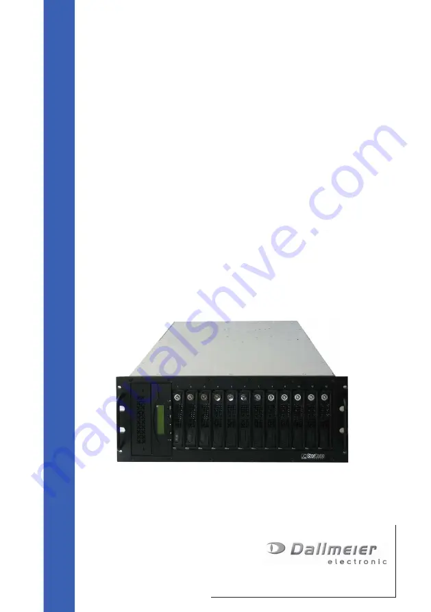
External storage system
DAS-100/200
Rev. 1.0.1 / 060612
English
Page 1: ...tion and Commissioning Installation and Commissioning Installation and Commissioning Installation and Commissioning Installation and Commissioning External storage system DAS 100 200 Rev 1 0 1 060612...
Page 2: ...ceiving written permission from Dallmeier electronic GmbH Co KG We reserve the right to make technical modifications The manufacturer accepts no liability for damage to property or pecuniary damages a...
Page 3: ...AS 100 Single Host 14 4 3 Connection assignments DAS 200 Dual Host 15 5 Installation and connection 17 5 1 Requirements at the installation site 17 5 2 Installation sub rack 18 5 3 Connection 19 5 3 1...
Page 4: ...4 DAS 100 200 Dallmeier electronic GmbH Co KG...
Page 5: ...ally provided The target audience of this document is exclusively specially trained and authorized professionals installers Storage of documentation Store this document in an accessible location near...
Page 6: ...PORTANT denotes information for preventing damage incorrect configurations or incorrect actions NOTE A NOTE offers information on principles special features and efficient procedure as well as general...
Page 7: ...orized professionals installers In as far as not expressly specified otherwise this specification also applies to the maintenance testing and repair of the unit Read and understand instructions Read t...
Page 8: ...r impair it in its function The ambient air is drawn in to cool the unit The ambient temperature should not exceed 35 C 95 F in order to ensure sufficient cooling Ventilation Overheating of the unit c...
Page 9: ...ords You should change the default passwords for security reasons Ensure that you will always remember the current passwords of the system Losing the administrator password in particular could require...
Page 10: ...0 Dallmeier electronic GmbH Co KG Disposal Disconnect the unit from the power supply Then remove the power cable and all the expansion components peripheral devices Return the unit to your respective...
Page 11: ...Dual Host 2 x Power cable 2 x Serial cable 2 x SCSI cable HD68 3 2 Transportation and packaging Store the original packaging for transportation at a later date Dallmeier electronic is not responsible...
Page 12: ...he event of a defect hard disk drives can be replaced without any problem whilst the system continues to operate In addition a hard disk drive can be configured as the hot spare so that it automatical...
Page 13: ...Co KG 4 Views and connection assignments 4 1 Front view Status LED unit ready blue Status LED drive active red Status LED drive drive ready blue fault red drive active orange HDD module Sub rack Key...
Page 14: ...s jack Mains connector Power pack module 1 or Power pack module 2 On Off switch Fan module 1 or Fan module 2 This module is not used Modem interface not used Serial interface RS 232 SCSI In Out channe...
Page 15: ...ins connector Power pack module 1 or Power pack module 2 On Off switch Fan module 1 or Fan module 2 This module is not used Modem interface not used Serial interface RS 232 SCSI In Out channel 1 LVD S...
Page 16: ...16 DAS 100 200 Dallmeier electronic GmbH Co KG...
Page 17: ...ibed environmental conditions must be complied with at the installation site see technical data Overheating in particular can cause permanent damage to the unit The ambient temperature may not exceed...
Page 18: ...vailable in the 19 rack IMPORTANT Serious damage to the sub rack A 19 rack with support rails is essential for installing the sub rack 1 Slide the sub rack fully into the 19 rack IMPORTANT Serious dam...
Page 19: ...H1 in DMS DLS 1 CH2 in DMS DLS 2 IMPORTANT No data recording The CH 1 out interface of the last DAS in the chain must always be disabled with a terminator in a cascading system The supplied terminator...
Page 20: ...DAS systems with the black serial cable using the RS232 interface The serial interface can be freely selected at the DMS DLS COM1 or COM2 Even in the case of a dual host system or a cascading storage...
Page 21: ...ected via IDE As in the example above an internal CD DMS drive must be marked as the backup device if this has not already been done check in the Bak column The external storage system is displayed as...
Page 22: ...22 DAS 100 200 Dallmeier electronic GmbH Co KG...
Page 23: ...pack to the power supply 2 Switch on the two power packs 3 The fans for the power packs will start to turn and the status LED will be lit green 4 The DAS will now boot and initialize the hard disk dri...
Page 24: ...of the DAS has been completed all the recorded pictures may be lost To ensure that you adhere to the starting sequence we recommend that you use a programmable socket strip for the entire system This...
Page 25: ...t the normally specified gross capacity but the number of sectors used Contact the Dallmeier Support Team if you are in any doubt IMPORTANT Possible damage to the RAID system and thus loss of data The...
Page 26: ...the same time IMPORTANT Possible damage to the drive and thus loss of data Ensure that the host does not access the drive whilst the HDD module has been removed 1 Ensure that the Drive active LED is...
Page 27: ...ectrostatic discharge caused by touching them Ensure that you are electrostatically discharged earthed before you touch the module Wear suitable ESD shoes or an earth strap 7 1 2 Install the HDD modul...
Page 28: ...ing 3 Push down on the handle of the HDD module Lock the module using the key The re establishment of the RAID system is started after the new HDD module has been installed This process may take up to...
Page 29: ...e power pack module off A 2 Disconnect the power pack from the power supply by removing the non heating appliance cable B The Status LED will no longer be lit C WARNING Danger of death from electric s...
Page 30: ...ARNING Danger of death from electric shock Never connect the non heating appliance cable to the power pack module before sliding the module in 1 Ensure that the power pack module is correctly aligned...
Page 31: ...pack will start to turn and the status LED will be lit green The power pack module is operational again 7 3 Fan module 7 3 1 Remove the fan module 1 Undo the two screws of the fan module until they a...
Page 32: ...ossible damage to the fan module and or sub rack Ensure that you slide it straight Do not use any force z The fan module is inserted correctly when it has been fully slid in and engaged z The front co...
Page 33: ...Interface Protocol Ultra320 Transfer rate 320 MB Sec Connection VHDCI68 HD68 Serial interface RS232 DB9 RS232 Mini USB not used Modem not used Power pack module Number 2 Power 460 W per module Redunda...
Page 34: ...y DAS 100 max 4 DAS 100 110 per channel DAS 200 no Sub rack Measurements W 430 x H 177 x D 535 mm Model 19 Rack Mount housing 4 HE Weight without HDDs approx 26 4 kg Operating environment Temperature...