Electrical component
223
1
2
3
4
5
6
7
8
9
10
11
Chapter 11
QS07
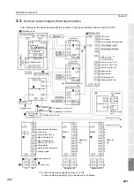
3-3.
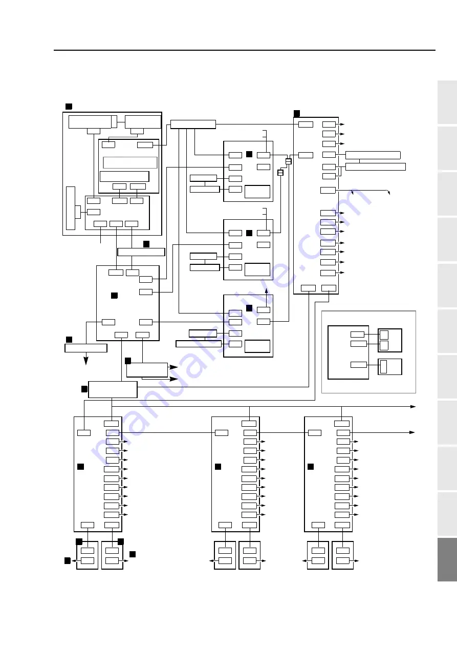
Electrical system diagram (Multi-head machine)
The numbers in the figure accord with the numbers in the layout drawing of each cards. (p.221)
Power supply card
Head card
Tension base card
X motor
Machine card
Picker solenoid
1st to the last head
Sequin air valve L (OP)
Sequin air valve R (OP)
Beam sensor
Sequin air sensor (OP)
X encoder
1H/2H
3H/4H
5H/6H
1H
Main shaft
X driver
Y driver
Main shaft driver
Main shaft fixed position sensor
Beam sensor
Start/stop switch
To head card of 7H/8H
Limit switch
Origin sensor
CN10 CN6
CN2
CN4
CN1
CN7
CN3
CN12
CN8
CN3
CN5
CN6
CN7
CN10
CN21
CN19
CN18
CN16
CN11
CN20
CN9
CN1
CN1
CN2
CN2
CN3
CN1
CN2
CN6
CN9
CN7
CN3
CN1
CN2
CN6
CN9
CN7
CN3
CN1
CN2
CN6
CN9
CN7
CN22 CN15
CN11
CN28
CN29
CN10
CN27
CN26
CN25
CN13
CN7
CN1
CN24
CN9
CN2
CN12
CN8
CN3
CN5
CN6
CN7
CN10
CN21
CN19
CN18
CN16
CN11
CN20
CN9
CN1
CN1
CN2
CN2
CN12
CN8
CN3
CN5
CN6
CN7
CN10
CN21
CN19
CN18
CN16
CN11
CN20
CN9
CN1
CN1
CN2
CN2
CN4
CN11 CN7
CN9
CN6 CN5 CN2
Operation panel
Backlight inverter
Switch card
Capa
c
ito
r card
Emergency
stop switch
5 V, 12 V power supply
Driver
CPU card
Y motor
Y encoder
Driver
CPU card
Driver
CPU card
Upper thread holding hook
Jump motor
Sequin motor L/R (*3)
Upper thread lock
Jump motor
Upper thread holding hook
Position marker
TC sensor card
CN8
CN20
Color change encoder
Color change motor
Noise filter
CN8
24 V power
supply
To head card of 9H to 16H
To head card of 17H/18H
To head card of 7H/8H
Terminal base
1
2
3
4
5
5
10
10
12
11
11
Table up/down limit
In case of single-side equipping of sequin (L or R)
In case of both-side equipping (LR), extension card is attached.
Main shaft sensor
CN4
CN1
CN1
CN1
CN5
CN2
LCD panel
CN9 CN12
USB hub
CN10
Carrier card
CPU card
Carrier card
CN4
CN11
LAN
USB
CN2
USB connector
CN13
card
I/F connector
A
Same as
left
10
12
*3:
Upper thread lock
Sequin motor L/R (*3)
Same as
left
Same as left
Same as left
2H
*2:For head card of 1H to 8H
24 V power
supply
(*2)
ATH motor
ATH sensor
Color change potentiometer
9
6
7
8
To [A]
(Right in the
middle column)
card
Limit switch
Origin sensor
Summary of Contents for TEMX-C Series
Page 13: ...To search from the menu key ...
Page 25: ...Inspection before starting work 12 Chapter 1 ...
Page 39: ...How to use each part 26 Chapter 2 ...
Page 40: ... E 1 2 3 4 5 6 7 8 9 10 11 27 PT10 Chapter 3 Screen 1 Screen display 28 2 Message display 31 ...
Page 147: ...Other functions that must be remembered 134 Chapter 5 ...
Page 171: ...To move the frame to the position registered 158 Chapter 6 ...

