background image

63

Configuring the T-Comfort 930 DSL

Configuration

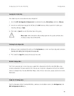
3. The basic settings switch is designed as a key switch. The location of the switch can be found in the 

chapter entitled 

Interface Cards

 starting on page 31. Press and hold the switch.

4. Replace the power plug in the mains socket. Wait about 30 seconds until the indicator on the front of the 

T-Comfort 930 DSL constantly flashes.

5. Disconnect the power plug from the mains socket again.

6. Release the key switch.

The system data is now reset.

7. Replace the power plug in the mains socket.

The T-Comfort 930 DSL will now reboot in the default configuration. The procedure is completed when all 

connected system terminals show the time on their displays.

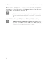
8. Log on to the Web console (see 

Starting the Web Console

 on page 57). Configure the T-Comfort 

930 DSL (possibly by loading a saved configuration; see 

Saving and Loading the Configuration on 

page 60

). 

Generating Your Own MoH Files

The T-Comfort 930 DSL comes with an internal MoH file for Music on Hold. The T-Comfort 930 DSL product 

CD contains a number of MoH files with different volume levels, which you can load at a later time as nec-

essary. 

The file format for non-resident Music on Hold is *.wav. You can also save your own MoH in a *.wav file and 

load it into the T-Comfort 930 DSL. 

If you have a Windows operating system, you can use the “Sound Recorder” program to generate your own 

MoH file. This program is usually located in the Windows directory called “Multimedia”. 

The MoH file must be coded with 8000 Hz, 8 bit mono in accordance with CCITT, A-Law. This coding is 

required for the T-Comfort 930 DSL and can be set in the “Sound Recorder” when you save the file under 

Format

 (CCITT, A-Law) and 

Attributes

 (8000 Hz, 8 bit mono). The maximum allowable size for a MoH file is 

Summary of Contents for 930 DSL

Page 1: ...T Comfort 930 DSL Mounting and Commissioning...

Page 2: ......

Page 3: ...cautions 19 Mounting Location 21 Wall Mounting 21 Installing an Expansion Set 22 Installing Interface Cards 25 V 24 and Doorstation Equipment Slots 25 Slots for Additional Interface Cards 26 Available...

Page 4: ...r Ports 43 COM Port 45 LAN Port 45 AccessoriesandAdapters 46 Upn Adapter 46 Audio Adapter 47 Device Combinations 49 Configurations without Plug in Power Supply Range up to 500 m 49 Configurations with...

Page 5: ...ail 61 Loading SW Updates 61 Resetting the System Data 62 Basic Hardware Settings Switch 62 Generating Your Own MoH Files 63 ConfigurationExamples 65 T Comfort 930 DSL in Computer Networks 65 Introduc...

Page 6: ...d PBX into Operation 78 Notes 79 PBXNetworking 81 Connections 81 Protocol Q SIG or DSS1 82 Master Slave 82 L1 Clock 83 Types of Point to Point Connections 84 Direct Connection 84 Connection via an Act...

Page 7: ...Queue 99 Introduction 99 Activation of Queues 100 Call Forwarding 100 Pickup 101 Hunt Groups 101 Examples of Use 101 Enquiry Station for an Operator with Two System Telephones 101 Group of Three Enqui...

Page 8: ...ftware 111 Setting up TAPI 111 Setting up NET CAPI 113 Using the Systray Display 114 Browser for Telefonie Assistent and Comfort Pro A Hotel 115 Setting up Video Telephony 116 Synchronising the PC Clo...

Page 9: ...126 Branch Settings 127 E mail Function 128 E mail Access 129 FrequentlyAskedQuestions 130 General Hardware 131 Telephony 132 DECT 134 LAN 135 Internet 136 More Questions 138 TechnicalSpecifications...

Page 10: ...8...

Page 11: ...ards without changing the system The base module of the T Comfort 930 DSL s version 1can be expanded to connect an door entrance intercom and a serial interface For a T Comfort 930 DSL version 2 we re...

Page 12: ...can also be connected to the DECT enabled Upn ports on interface cards An analogue port is used by standard analogue devices If the CNIP calling name identification presentation feature is supported...

Page 13: ...SAPI 16 can also be established between several S0 interfaces of the T Comfort 930 DSL Simultaneous connections are distinguished by means of a TEI Terminal Endpoint Identifier X 31 packet data can b...

Page 14: ...Comfort 830 handset sets up a data connection with the T Comfort 930 DSL via the DECT air interface The remainder of the connection set up is either direct through an ISDN B channel or indirect throu...

Page 15: ...and voice information system For more information refer to the user guides called Comfort Pro A IAB integrated answering machine and Comfort Pro A IAM interactive call manager You can optimise your t...

Page 16: ...ed on the three Upn ports Analogue terminals with the telephone numbers 10 to 13 are configured on the four a b ports The T Comfort 930 DSL is configured ready for operation in Germany Analogue device...

Page 17: ...numbers can be dialled from all configured telephones External lines must be seized by entering a prefixed code Least cost routing is not active As soon as LCR is configured users can make calls via...

Page 18: ...if this feature has been ordered from the network operator The white list black list and call filters are not preconfigured and thus not active If these lists are con figured they can be activated fo...

Page 19: ...ion to system terminals is possible There are no user accounts configured for the sending of e mails the authorisation for sending e mails is not deactivated The multi company variant is not activated...

Page 20: ...DHCP or PPP Gateway address 192 168 99 254 Domain name domain Domain name server 192 168 99 254 PPP addresses 192 168 100 0 to 192 168 100 10 DHCP addresses 192 168 99 129 to 192 168 99 148 You can ch...

Page 21: ...are The T Comfort 930 DSL expansion set consists of One expansion module One AC adapter with a connection cable to supply the expansion module with power One mounting set with which to install the exp...

Page 22: ...talling electrical and electronic components of the T Comfort 930 DSL Only devices that deliver safety extra low voltage SELV may be connected to the T Comfort 930 DSL Proper use of authorised devices...

Page 23: ...ated location away from direct sources of heat Do not position the T Comfort 930 DSL in front of or above heat sources such as radiators in direct sunlight behind curtains in small unventilated damp r...

Page 24: ...nplug the plug in power supply from the socket You should not install the expansion module or install or uninstall additional interface cards while the T Comfort 930 DSL is turned on 2 Open the housin...

Page 25: ...Carefully press the expansion module at the top and bottom right pushing it into the locking hooks pro vided see A and B in the diagram Secure the expansion module using the Phillips screws provided i...

Page 26: ...sh an Ethernet connection between the LAN port of the basic module and the LAN1 port of the expansion module see also Positions of the Ports starting on page 30 To do this use the short Ethernet conne...

Page 27: ...ment Slots Slots on the basic module only T Comfort 930 DSL Version 1 The T Comfort 930 DSL Version 1 has two smaller slots in which special interface cards can be operated V 24 and doorstation equipm...

Page 28: ...when the T Comfort 930 DSL is operational again To do this call up the PBX Configuration Ports Slots menu page The Status column in the table displays a green tick beside the name of the interface car...

Page 29: ...aution Static charges can damage electronic components Pay attention to the regulations re garding the handling of electrostatically sensitive components 3 Carefully insert the interface card in the s...

Page 30: ...installing the expansion set and additional interface cards see Installing an Expansion Set starting on page 22 and Installing Interface Cards starting on page 25 One S0 port to connect to an externa...

Page 31: ...r interfaces and ports can be added by installing the expansion set and additional interface cards see Installing an Expansion Set starting on page 22 and Installing Interface Cards starting on page 2...

Page 32: ...the basic module T Comfort 930 DSL Version 1 Position of the ports on the expansion module T Comfort 930 DSL RJ45 S01 RJ45 S02 LAN V 24 Sensor 1 2 a b 1 2 a b 3 4 S02 Upn 2 3 DC in Sensor 3 Upn1 Defa...

Page 33: ...S0 are switchable internally externally 4 x Upn Upn are DECT enabled 8 x Upn Upn are DECT enabled 2 x S0 and 6 x Upn Upn are DECT enabled S0 are switchable internally externally 2 x S0 and 6 x a b S0...

Page 34: ...n 1 4 Upn 1 3 Upn 1 5 Upn 1 6 Upn 1 7 Upn 1 8 Slot 1 Slot 2 Slot 3 Upn 2 1 Upn 2 2 Upn 2 3 Upn 2 4 Upn 2 5 Upn 2 6 Upn 2 7 Upn 2 8 S0 1 1 Slot 1 Slot 2 Slot 3 S0 1 2 Upn 1 1 Upn 1 2 Upn 1 3 Upn 1 4 Up...

Page 35: ...1 4 ab 1 3 ab 2 1 ab 3 1 ab 2 2 ab 3 2 ab 2 3 ab 3 3 ab 2 4 ab 3 4 Slot 1 Slot 2 Slot 3 ab 1 1 ab 1 2 ab 1 4 ab 1 3 ab 2 1 ab 3 1 ab 2 2 ab 3 2 ab 2 3 ab 3 3 ab 2 4 ab 3 4 ab 1 5 ab 1 6 ab 1 7 ab 1 8...

Page 36: ...in the S0 port configuration in the Configurator on the Web console You can connect up to eight terminals on every internal S0 bus up to three of the terminals can operate without an external power s...

Page 37: ...witched between internal and external operation In contrast to the basic module the expansion module does not provide any additional RJ45 jacks for external S0 ports Therefore you can also use the pre...

Page 38: ...00 300 500 system telephone using a twin wire cable The maximum permissible length of the twin wire cable on a Upn port is 500 m This line may only be laid inside buildings The maximum permissible len...

Page 39: ...sor port Only use entrance intercoms and door openers complying with the German FTZ Guideline no 123D12 LAN Port The LAN port on the basic module enables integration of the T Comfort 930 DSL into an e...

Page 40: ...IP protocol of the LAN Connecting the T Comfort 930 DSL to the network via T ISDN and T DSL Connection of the T DSL modem is via a crossover twisted pair line You can also use a switchable port on th...

Page 41: ...in When the first external out going call is made the time and date are set to the current value as given by the exchange With the T Comfort 930 DSL Version 2 date and time generally will be adjusted...

Page 42: ...rnally S0 ports on interface cards can also be switched external internal It is not possible to use both assignments simultaneously Up to eight devices per bus ISDN telephones ISDN fax machines ISDN b...

Page 43: ...ports of Upn interface cards If this base station is connected to a Upn port of an interface card four simultaneous calls are possible with the handsets If the base station is connected to two Upn po...

Page 44: ...xternal music on hold Incorrect input impedance can cause irreparable damage to the T Comfort 930 DSL Voice Mail If you are using an external voice mail system it must be capable of handling the numbe...

Page 45: ...tering the code procedure 102 The DoorLine intercom system can be connected to any a b port However you can use only one DoorLine with the T Comfort 930 DSL For details on installing and configuring t...

Page 46: ...am shows the usage of the PVG 402 0 module which merely serves as an example Other modules can also be operated such as its successor PVG 602 01 Door bell Siedle 12 11 9 Sensor Actor1 Actor2 a b1 Door...

Page 47: ...0 DSL into your corporate network local area network and thus use it among other things as an IP router for accessing the Internet The LAN ports of the Ethernet switches on the expansion module proces...

Page 48: ...al Support if you need further equipment such as headsets second handsets recording devices etc Upn Adapter The Upn adapter is an adapter with a Upn port for connecting another T Comfort 630 730 830 s...

Page 49: ...for Socket Assignment 1 Ear cap second handset headset active speaker or micro phone RJ 10 4 pin Western socket 1 microphone 2 speaker 3 speaker 4 microphone 2 Recording device relay con tact generat...

Page 50: ...dset headset loudspeaker Typical impedance 150 30 ohms Typical sensitivity 94 dB 1 mW 0 dB 20 Pa Active speaker Max output voltage 1 Vrms at input impedance 10 kOhms Recording device audio input Typic...

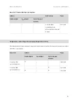
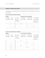
Page 51: ...pad modules 330 mW These symbols are used in the following tables This combination is possible Reduced tone ringing open listening and hands free talking volume possible Configurations without Plug in...

Page 52: ...Basic Unit T Comfort 830 System Telephone Add ons 2nd Terminal Power Audio adapter Upn adapter Up to 3 keypad modules 1140 mW 1470 mW 1730 mW T Comfort 630 system telephone without adapter 2335 mW T...

Page 53: ...um power consumption of 2 2 W is not exceeded T Comfort 830 system telephone withoutadapterorkeypad module 2475 mW Basic Unit Add ons Power Audio adapter Upn adapter Up to 3 keypad modules T Comfort 7...

Page 54: ...ystem Telephone Up to 3 key pad modules Audio adapter Upn adapter and plug in power supply T Comfort 630 without adapter T Comfort 730 without adapter T Comfort 830 without adapter and with 1 key pad...

Page 55: ...tain system services carry out further system maintenance use PC supported telephony functions read out call charge information access the T Comfort 930 DSL telephone book The Web console has an integ...

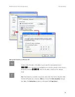
Page 56: ...ws 2000 XP under Start Settings Network connections Local Area Connection Open the dialogue box Local Area Connection Properties and then the dialogue box Internet Protocol TC IP Properties see figure...

Page 57: ...a connected system telephone You can also view the net mask by en tering the procedure 183 The PC s IP address must be in this network range N Note Deactivate any connection via a proxy server which...

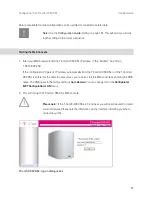
Page 58: ...link with the icon configured on the desktop under step 1 Enter Admin istrator without a password as your user name 4 Start the Web browser Enter http 192 168 99 254 in the address box You will see th...

Page 59: ...configuration PC gets its IP address automatically from the T Comfort 930 DSL or if the T Comfort 930 DSL is entered as the domain name server you can also start the Web console by entering the DNS n...

Page 60: ...ent international external calls from the terminals for example while you are configuring the T Comfort 930 DSL and the users T Comfort 930 DSL dialogue box for initial access 5 The software opens a d...

Page 61: ...ishing the Configuration 1 When you have completed all the settings in the Configurator you must save the configuration see also Saving and Loading the Configuration on page 60 2 Then select the Log o...

Page 62: ...y Z zzz Set NET mask H 183 Z system PIN Z www Z xxx Z yyy Z zzz Example Enter H 1830000 192 168 99 254 If required initiate a system restart with this procedure H 1 8 5 Z system PIN Use the PIN you en...

Page 63: ...nation of the message Further extra parameters such as the port number when a trunk line drops out are also provided The mail account for this service Account for LOG filter is configured in the Confi...

Page 64: ...e help Proceed as follows 1 In the Configurator call up the SYS Configuration Restart menu 2 Click on Restart with Defaults 3 Confirm this by pressing OK when the query dialogue box opens Basic Hardwa...

Page 65: ...e T Comfort 930 DSL possibly by loading a saved configuration see Saving and Loading the Configuration on page 60 Generating Your Own MoH Files The T Comfort 930 DSL comes with an internal MoH file fo...

Page 66: ...al and external calls N Note If you don t have the Sound Recorder program or the appropriate codec on your Windows operating system you should install these components from your Windows CD Load your M...

Page 67: ...on a PC the T Comfort 930 DSL central telephone book and your personal telephone book as well as to the company telephone book if the multi company variant is activated In addition the T Comfort 930 D...

Page 68: ...the same and the last number is uniquely assigned to a specific device in the LAN On the Internet unique addresses assigned by a special organisation created for this purpose are used Within a LAN yo...

Page 69: ...information on the names and IP addresses for which it is responsible For all other information a DNS server contacts other DNS servers For the establishment of every connection from the workstation...

Page 70: ...he Configurator home page can be called up In a peer to peer network Windows network the workstations each have a name which is displayed in the network environment These NetBIOS names can differ from...

Page 71: ...s not used in the Inter net as the domain name my firm co uk for example RAS Access You can establish a connection to the T Comfort 930 DSL from an external PC via an ISDN card The necessary IP settin...

Page 72: ...tings via DHCP for all workstations On starting the T Comfort 930 DSL requests IP settings via DHCP If this request is responded to the T Comfort 930 DSL uses the IP settings received You can then use...

Page 73: ...ocumentation Internet Access You can also use the T Comfort 930 DSL as an Internet access server in a LAN with an IP enabled server To do this you must enter the T Comfort 930 DSL IP address on the se...

Page 74: ...should coordinate with the network administrator the IP address space which can be assigned to an external computer dialling in and enter it in the Configurator NET Configuration RAS ISDN menu under...

Page 75: ...server whose address the T Comfort 930 DSL does not make known to the workstation when dialling in with ISDN For this reason you enter the address of a WINS server manually in the network settings of...

Page 76: ...nnection after a certain period of time if no data are being transmitted Unfortunately programs other than those typically intended to access the Internet such as your browser or your e mail software...

Page 77: ...s in the Internet is e mail E mails are buffered in individual e mail accounts on a mail server Mail servers are operated by ISPs for example With the T Comfort 930 DSL you can set up one or more e ma...

Page 78: ...following prop erties IP addresses are transported in the useful load e g NetBIOS over TCP IP The protocol requires an active inward directed connection establishment e g ICQ The protocol will functi...

Page 79: ...ly function like a single PBX with a higher number of ports The master PBX controls the slave PBX The fol lowing PBXs from the product family can be used for cascading Functionality of PBX Cascading P...

Page 80: ...If necessary install the add on module for the master system If you use an T Comfort 930 DSL as the slave system you also have to install an add on module 5 Connect the two modules by means of two sui...

Page 81: ...can see that the initialisation has been completed from the display on the system telephone connected to the slave system Notes Observe the following when operating a cascaded PBX system All Upn S0 an...

Page 82: ...tion A memory card installed in the slave system Comfort Pro A IAB integrated answering machine cannot be used To operate the slave system again normally you must reset it to its factory settings refe...

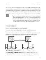
Page 83: ...Settings dialogue under System linking Refer also refer to the corresponding help topics in the T Comfort 930 DSL online help N Note If you do not need the features of PBX networking the simplified co...

Page 84: ...rotocol however In par ticular the identifier indicating whether a call is internal or external cannot be transmitted using DSS1 Both protocols implement communication on several protocol layers L1 La...

Page 85: ...han one port with the setting L1 Type Slave is configured on anT Comfort 930 DSL and the setting L1 sync possible has been activated then one of the ports is automatically defined as the L1 clock sour...

Page 86: ...the protocol slave for all three layers Direct connection Use the RJ45 jacks on one of the external S0 ports for an S0 connection between two T Comfort 930 DSLs You can use the corresponding pressure...

Page 87: ...the network operator or from a clock generator connected by wire Connection via the Public Network Point to point connections via the public network of a network operator can be used for bridging dis...

Page 88: ...above example the following trunk groups are configured for PBX 1 Two S0 lines in a multi terminal configuration to the network operator which are assigned to the A trunk group Two S0 point to point...

Page 89: ...t connection via PBX 3 the system tries again via trunk group A The prefix necessary for this can be configured with the route The user does not get a busy signal until the attempt to set up an indire...

Page 90: ...rcular switching To avoid this a transit counter is incremented whenever a connection is switched through on Q SIG lines When the configured maximum value is reached further switching stops Technical...

Page 91: ...configuration for the routes to be reseized t If for example you are configuring a route which can be seized using routing code 5 and have selected one or more bundles for this route change the Prefix...

Page 92: ...required features Explanation of Keys The team functions are programmed on the call keys of the T Comfort 630 730 830 telephones Depending on the terminal different numbers of call keys are available...

Page 93: ...at has been programmed with the same number For example the team key with the number 11 calls all trunk keys with the number 11 Busy key The purpose of a busy key is to make the busy status of other t...

Page 94: ...a project group within a department Calls from customers of this group can then be answered by any team member who is not busy The team members can call each other by the team keys A busy key can be...

Page 95: ...on the call number 10 trunk key TrK 10 executive s office He can also answer calls from his parallel telephone In addition a private line is configured for both of the executive s tel ephones trunk ke...

Page 96: ...signal on one s own telephone flashing trunk key LED The parallel telephone will indicate calls only by an optical signal Time delayed acoustic signalling can be configured for TrK 10 on the secretar...

Page 97: ...ey The team members can call each other via the team keys For example Miller can call number 12 by pressing TK 12 the call is then signalled to Smith s telephone on TrK 12 Line Busy Indication If a li...

Page 98: ...ers can use these numbers for answering as well as making calls t In this team configuration it is useful to program one of the function keys on each tele phone with the Hold function A call e g for T...

Page 99: ...number of call numbers can be managed efficiently with the help of team functions Each team member has one T Comfort 830 system telephone with all call keys programmed as trunk and team keys Example...

Page 100: ...l lines e g TrK 10 and TrK 11 by pressing the appropriate key toggling Every call on a trunk key can be transferred to any other party by means of the R key For more information refer to the chapter e...

Page 101: ...by a brief tone in the loudspeaker and in the display If calls are in the queue a number at the beginning of the second line of the display on the T Comfort 830 and Comfort Pro P 500indicates how ful...

Page 102: ...ncoming menu Central welcoming texts can be recorded using the program package Comfort Pro A IAB integrated answering machine You should configure a new user group e g Operators and activate the autho...

Page 103: ...s removed from all other parallel queues Examples of Use N Note Ports on a Upn interface card are DECT enabled so that DECT base stations can be connected to operate cordless system terminals Enquiry...

Page 104: ...830 Comfort Pro P 500 which activates deactivates a call for warding immediately to the telephone number of the mobile T Comfort 830 handset Comfort Pro CM 300 in the menu Call diversion Divert phone...

Page 105: ...onfiguration Call Distribution Incoming PTP route all incoming calls to the number of the hunt group In the Configurator create a new group called Operators under User Manager User groups Activate Cal...

Page 106: ...In contrast to Example 1 further calls do not have to be processed after the sign off as the calls are also registered in the queues of the other signed on enquiry stations N Note The last enquiry sta...

Page 107: ...wever It is possible to configure the T Comfort 930 DSL for each company and define the extent to which the features of the system may be used In brief the features of the multi company variant are as...

Page 108: ...the corresponding company or its staff correctly the existing trunk groups must be uniquely assigned to the companies see Assigning Trunk Groups starting on page 108 5 In the case of outgoing externa...

Page 109: ...example the respective configuration is changed to the default company The name of the default company can be changed but the default company itself cannot be deleted Assigning Users For each user you...

Page 110: ...the company is irrelevant the charges are assigned according to the source principle Charges are billed to the company to which the user belongs who set up the connection The T Comfort 930 DSL recogn...

Page 111: ...f the T Comfort 930 DSL which the users may already be familiar with from the single company variant are available in the multi company variant These features can be used to the same extent and can be...

Page 112: ...his authorisation is useful if members of this group e g the Administrators service the entire system Foreign telephone books can only be edited in the Configurator in the Phone Book menu The number o...

Page 113: ...Follow the program instructions Further instructions for various options that are available are given below Setting up TAPI With a TAPI Telephony Application Programming Interface you can operate a C...

Page 114: ...s for the user who is currently logged on Click on New 5 In the following dialogue you provide information for the new connection In the Connection name box you can enter a descriptive name for the co...

Page 115: ...e Connections component Setting up NET CAPI With a CAPI driver common application programming interface Windows programmes are able to access services and functions of an ISDN card With a network base...

Page 116: ...ch you configured the CAPI telephone number in the User Manager see Step 3 You will find further information on the working of the NET CAPI driver and CAPI application programmes on the product CD Not...

Page 117: ...onfig uration dialogue Select Network Connections or Trunk Lines to produce a status dia logue Browser for Telefonie Assistent and Comfort Pro A Hotel You can simplify the daily use of the Telefonie A...

Page 118: ...g is already pre installed on the Microsoft Windows 2000 and XP operating systems Set up Microsoft NetMeeting 3 0 1 Connect a standard web cam to the workplace computer and install the driver 2 In the...

Page 119: ...e T Comfort 930 DSL as an SNTP server for such programmes SNTP with Windows 2000 Here you configure the SNTP server as follows 1 Log on as the administrator Start the Command Prompt under Start Progra...

Page 120: ...x will then open 2 Click on Add Select the Directory Service command from the pop up menu The Internet Connection Wizard dialogue box for Internet access will then open 3 Under Internet directory LDAP...

Page 121: ...Upn Ports starting on page 36 2 Configure the T Comfort 730 DECT base station in the Configurator using the PBX Configuration Ports Upn menu 3 Install the software of the T Sinus 61data T Sinus 620da...

Page 122: ...Internet access in the T Comfort 930 DSL Configurator menu NET Configuration WAN You can edit create suitable filter lists for the Internet access in the NET Configuration Firewall menu 9 Configure t...

Page 123: ...uring ports and terminals Configuring Easy Access This chart guides you through TCP IP settings for the T Comfort 930 DSL Configuring ISP Settings These instructions support you in configuring the Int...

Page 124: ...e user groups and users Set the system data Select the access type Connect the S0 Upn and analogue devices and configure them Configure the call distribution scheme User Manager PBX Configuration Save...

Page 125: ...n S0 interface Do you want to operate system telephones or DECT terminals Do you want to operate analogue terminals e g a fax machine Do you want to use a sensor contact e g for a door opener Do you w...

Page 126: ...erver Do you have a DHCP server in your network Do you have a computer network Enter the address range for the RAS accesses Gateway address DHCP adresses Domain name Client computers are informed of t...

Page 127: ...er list IN Filter list OUT Finished Gateway Yes No No Yes Configure T Online in NET Configu ration WAN Provider You will obtain the access data when you register Enter your provider s dial in data Spe...

Page 128: ...rights Select the filter lists Filter lists are created in NET Configuration Firewall Specify how many simultaneous connections are possible via this access Select from PAP CHAP and CLID Activate the...

Page 129: ...number Enter the local IP address Enter the local network mask Specify the user name with which the remote LAN can access a destination Specify the password with which the remote LAN can access a dest...

Page 130: ...onfiguration E Mail Access Have you made the network settings for the T Comfort 930 DSL Do you want to use e mail from the Internet Has an internal e mail server been configured in your LAN Do you wan...

Page 131: ...onfiguration LAN or NET Configuration WAN User Manager User Accounts No No Yes Yes Do you have access to a mail server in your network or in the Internet Do you have created mail account polls in the...

Page 132: ...nce with the T Comfort 930 DSL S Please note Repairs to the T Comfort 930 DSL should only be carried out by quali fied personnel The following LEDs indicate that the T Comfort 930 DSL is ready for ope...

Page 133: ...and the plug in power supply from the socket Take the housing cover off Is the Power Fine LED illuminated If not contact your service centre The AC adapter plug of the T Comfort 930 DSL may be defecti...

Page 134: ...to seize a trunk line Deactivate the corresponding S0 port in the Configurator PBX Configuration S0 menu One of the telephones is not functioning at all Make sure the telephone has been properly conne...

Page 135: ...ts S0 menu must also be configured as an MSN on the ISDN telephone itself For further information refer to the User Guide of your ISDN tele phone An ISDN telephone always rings if another telephone on...

Page 136: ...ort 830 Comfort Pro CB 300 base stations are installed the blinking LED indicates that synchronisation is not fin ished The LED of the T Comfort 830 Comfort Pro CB 300 is continuously lit up but one o...

Page 137: ...nstalled an add on module also check the LAN LEDs of the Ethernet switch The Ethernet line between the basic module LAN port and the add on module LAN1 port are properly con nected if the centre LED l...

Page 138: ...erent seg ments you can enter extra static routes in the NET Configuration LAN Routes menu In our network the T Comfort 930 DSL dynamically issues the IP addresses by DHCP Can I firmly assign the IP a...

Page 139: ...Internet connection must also be specified in the respective user profile Configurator User Manager User menu With the T Comfort 830 handset the Internet can be accessed either directly via the remot...

Page 140: ...een granted RAS access rights Configu rator User Manager User Groups menu For information on the installation of software and on configuring Internet access refer to the T Comfort 830 handset s user g...

Page 141: ...module and power supply unit 1 900 g Add on module and power supply unit 1 000 g S0 ports Euro ISDN external S0 external for basic access DSS1 protocol Basic module 1x Add on module Euro ISDN switchab...

Page 142: ...4 x Upn 8 x Upn 2 x S0 and 6 x Upn Supply voltage 40 V 10 Supply power 3 VA per Upn bus Range 1000 m a b port for analogue terminals with pulse or DTMF dialling flash duration of 60 to 310 ms Basic m...

Page 143: ...limits that should be observed when configuring the T Comfort 930 DSL Doorstation equipment module for connection of doorstation equipment Basic module 1x optional Contact load of actor 2 A 125 V Volt...

Page 144: ...re updates 61 Remote configuration 59 Resetting the system data 62 Saving and loading the configuration 60 System prerequisites 54 via V 24 port 10 Configuration examples 65 Introduction to TCP IP 66...

Page 145: ...basic setting switch 62 I Installation 19 Mounting location 21 Ports 28 Scope of delivery 19 Wall mounting 21 Intercom system 42 Interface cards 25 Interface cards installation 27 Interface cards ove...

Page 146: ...uipment 28 LAN 45 LAN basic module 24 29 LAN1 24 S0 28 29 Upn 28 29 V 24 29 45 Ports see Interfaces 34 Power failure 39 Q Q SIG 82 R Remote configuration 59 Resetting system data 62 Routes 87 S S0 por...

Page 147: ...2 Terminating resistor 34 Three member team 94 Time zone 117 Toggle team 97 Troubleshooting 130 Trunk key 91 T Sinus 61 data 119 T Sinus 620 data 119 U Unified team 96 Upn port pin assignment 36 Upn p...

Page 148: ...146 Index Notes...

Page 149: ...147 Index Notes...

Page 150: ...148 Index Notes...

Page 151: ......

Page 152: ...As of 01 09 2006 Deutsche Telekom AG T Com Bereich Endger te Postfach 20 00 53105 Bonn...

Reviews: