D200-100-00
1
I56-3888-005
CONTENTS
Introduction . . . . . . . . . . . . . . . . . . . . . . . . . . . . . . . . . . . . . . . . 1
The FAAST LT Functional State Diagram . . . . . . . . . . . . . . . . . 1
Password Procedure (to enter Maintenance Mode)
2
An Introduction to PipeIQ™ . . . . . . . . . . . . . . . . . . . . . . . . . . . 2
Using PipeIQ™ to Configure and Monitor FAAST LT
. . . . . . . . 2
Connecting a PC to a FAAST Device for the First Time
2
Preparing to Configure or Monitor a FAAST LT Device
3
Monitoring a FAAST LT Device
3
Important Notes on Altering FAAST LT Settings
3
Configuring a FAAST LT Device
3
Sending a Configuration to a FAAST LT Device
4
Time and Date: Setting the Real Time Clock
4
Setting the Alarm Level (Stand Alone Versions Only)
4
FAAST LT Alarm Mode (Loop Based Versions Only)
4
Setting the FAAST LT Device Fan Speed
4
FAAST LT
FIRE ALARM ASPIRATION SENSING TECHNOLOGY
®
ADVANCED SET-UP AND CONTROL GUIDE
INTRODUCTION
The FAAST LT aspirating smoke detector is an advanced smoke
sensing system for use in early warning and very early warning
applications . The system continuously draws air from the controlled
environment through a series of sampling holes to monitor the
environment for smoke particulate . A range of sensing, operating
and output facilities can be configured in the FAAST LT unit by the
end user . This is accomplished by programming and downloading
control parameters from a PC running the proprietary software
application,
PipeIQ™
(Version 2.3 and above). This manual
describes how to monitor and configure the various operating
parameters available in a FAAST LT unit via the user interface
provided by PipeIQ™ .
Further PipeIQ™ Capabilities . . . . . . . . . . . . . . . . . . . . . . . . . . 5
Creating a Project 5
Designing a Pipe Layout 5
Creating Reports 5
PipeIQ™ Help 5
Appendices
A: FAAST LT Config. Parameters and Default Set-Up Values
. 6
Configuration Parameters
6
Default Set-Up Values - Stand Alone Versions
10
Default Set-Up Values - Loop Based Versions
12
B: FAAST LT Fault Codes . . . . . . . . . . . . . . . . . . . . . . . . . . . . .
14
C: Example Pipe Configurations
. . . . . . . . . . . . . . . . . . . . . . . .16
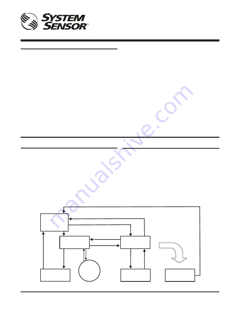
THE FAAST LT FUNCTIONAL STATE DIAGRAM.
In operation, the device can be in one of 6 possible states:
Initialization
Normal
Maintenance
Remote Maintenance
Service Mode
Power Out Of Range state
The routes in and out of these states are shown in the diagram
below .
MAINTENANCE
REMOTE
MAINTENANCE
SERVICE
MODE
POWER OUT OF
RANGE STATE
Power < 18V
Power > 32V
(Power-ON)
INITIALIZATION
NORMAL
DISPLAY
FAN
SPEED
USB
Disconnected
+ Cover Close
Cover Open +
USB
Connected
RESET +
DISABLE
RESET +
Password Enter
Cover
Open
Cover
Close
RESET + Password Enter (During Auto Speed Procedure)
Maintenance Timeout or after TEST + RESET + DISABLE (When Device Configuration has been Changed)
Maintenance Timeout or after
TEST + RESET + DISABLE
(No Need for Device to Initialize)
Power in Correct Range
Keep this document for future reference


