background image

In the event that firmware upgrades are necessary, and made available,
follow the procedures outlined below.  Users should be aware that turning
off power to the host computer, or the PC card reader during the firmware
upgrades will destroy the PC card reader. Synchrotech cannot accept
responsibility for units destroyed during this process.

If firmware upgrades are made available, the necessary files will be made
available, along with the updated instructions, at
http://www.synchrotech.com/firmware/

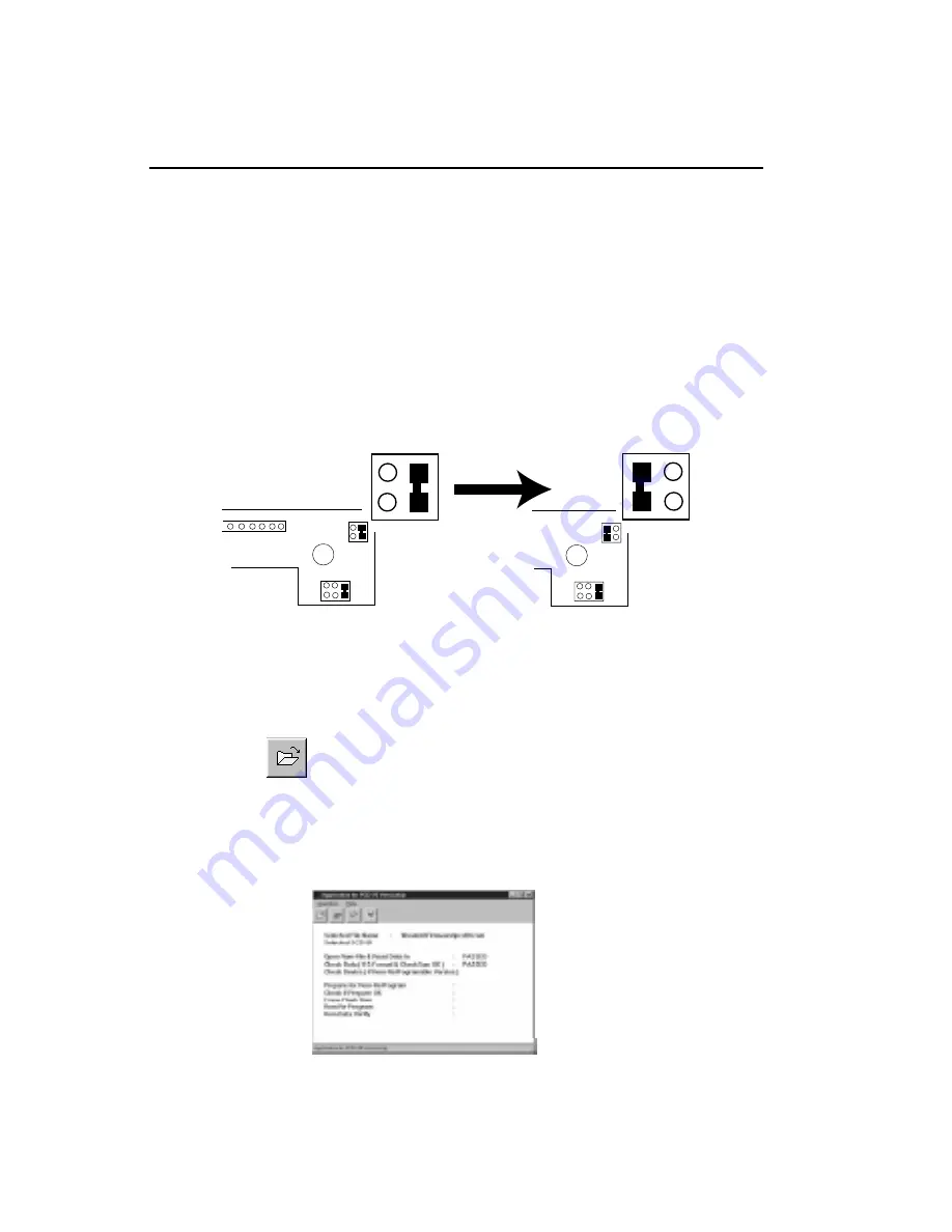
1. Open the unit and change the voltage jumper as shown in the following

diagram.

2. Boot the host computer to Windows.  Double click on the

pcdtool.exeicon.

3. Select the               “open file” icon.

4. Select the “pcd20.rom” file, and double click to open.  If the file is read

correctly, you will see the message “PASSED” after “open rom file”
and“read in data”, and “check data (if S-Format and Checksum OK)”.

23

9. FIRMWARE UPGRADE

Summary of Contents for PCM-CR-S2x

Page 1: ...IDENTIFYING THE PARTS BASIC OPERATIONS USE WITH A MACINTOSH USE WITH A WINDOWS BASE PC CONNECTIONS USER S MANUAL ver 1 0 PC CARD READER WRITER PCM CR S2x A Division of Synchronized Technologies Inc...

Page 2: ...arc Sun Ultra Sparc Digital Unix VMS AIX HP and Linux although Synchrotech does not offer Unix technical support help due to the wide variety of Unix systems It is assumed that users of Unix understan...

Page 3: ...n cords and power dividers can cause malfunctions Do not use outlets that have other large electrical appliances such as air conditioners and copy machines plugged in them To pr event electric shock N...

Page 4: ...se in an enclosed unventilated area Precautions for connection When connecting this unit to a personal computer or any other equip ment always first turn off the main power of the equipment to be conn...

Page 5: ...o correct the interference by one or more of the following measures 1 Re orient the receiving antenna 2 Re orient the computer with respect to the receiver 3 Move the computer further away from the re...

Page 6: ...connections with a computer 11 Termination 12 Use with other computers 13 To set the SCSI Id 13 5 Basic operations 17 Inserting the PC card 17 Removing the PC card 18 6 Using with a Macintosh compute...

Page 7: ...vailable as an option to mount removable media such as PC cards Compact Flash Smart Media and PCMCIA hard disks USING WITH A WINDOWS BASE PC If you do not already have a SCSI board installed follow th...

Page 8: ...PCM CR S2ISM USER S MANUAL This Manual USER S MANUAL This Manual OPTIONAL OPTIONAL Optional Accessories Macintosh PC 1 2 PCD 25 1 2 PCD 25 Macintosh Screws Terminators Macintosh Floppy Disk Macintosh...

Page 9: ...shows the access state of each slot It lights during read or write operations green With a Macintosh computer this indicator flashes even when no card is inserted 4 Lock Indicator Lamp This indicator...

Page 10: ...is connected securely and properly For internal units connect to one of the computers internal power cords 10 SCSI ID switch Use this switch to set SCSI ID number Do not to set the SCSI ID number to...

Page 11: ...ust have been previously mounted in the computer Consult the documentation that came with the SCSI board for installation instructions CAUTION Turn off the power to the computer and SCSI device s befo...

Page 12: ...the terminator to the SCSI connector not being used Internal Remove the cover over the terminators with a screwdriver Attach terminators and replace cover securely 1 External units come with an exter...

Page 13: ...SI devices to be connected can be changed SETTING THE SCSI ID The SCSI ID is a unique number assigned to each SCSI device Therefore two devices must not have the same ID number The SCSI ID is independ...

Page 14: ...ith SCSI ID jumpers as shown in the diagram In all cases two consecutive SCSI ID numbers must be available For Macintosh computers SCSI ID 0 is assigned to the built in hard disk drive SCSI ID 3 to th...

Page 15: ...Setting the SCSI ID on internal units To set the SCSI ID on the internal units set the three jumper pins as shown in the diagram The default SCSI ID is 4 15 1 2 3 4 5 6...

Page 16: ...C outlet or the computers internal power connector for internal units The cord should be firmly and securely connected and should be grounded before use Turning on the power Turn on the power for this...

Page 17: ...not to insert the PC card in the wrong direction If it is forced in the slot or PC card may be damaged or data on the card may be lost For SF series units which have one Smart Media slot be sure to in...

Page 18: ...is not formatted the following box appears Clicking on the Initialize button causes the PC card to be formatted initialized NOTE When the PC card is used for a digital camera the formatting is perform...

Page 19: ...e the mounted PC card If removed the following message appears on the screen Put the card back into the slot where it was NOTE For Macintosh computers the access indicator may flash on and off even af...

Page 20: ...card or SRAM cards on a Macintosh computer This software provides the following functions Automatically mounts the Macintosh formatted or DOS formatted PC Cards or other removable media NOTE The DOS...

Page 21: ...the SCSI card manual for details Technical questions concerning other SCSI cards should be directed to the SCSI card manufacturer not Synchrotech 1 Shut down the system and turn off the computer 2 Unp...

Page 22: ...er will work 5 Turn on the power to the reader and any other needed external devices 6 Turn on the computer and boot to Windows 7 Insert the PC card to be accessed NOTE Make sure everything is connect...

Page 23: ...are upgrades are made available the necessary files will be made available along with the updated instructions at http www synchrotech com firmware 1 Open the unit and change the voltage jumper as sho...

Page 24: ...Once the process is finished a congratulatory message will appear 7 Turn off the host computer and replace the voltage jumper to its original position 8 Restart your computer You now have new firmwar...

Page 25: ...ed The terminator is not activated Mac PC Manager is not installed Mac PC Manager is in contention with other control panels or extended functions The card is not properly inserted CORRECTIVE MEASURE...

Page 26: ...d is not properly inserted CORRECTIVE MEASURE Insert the power plug securely in an outlet or computer Use a standard SCSI cable Use a standard SCSI cable 6m or less in length Revise the settings accor...

Page 27: ...c for asynchronous transfer 4MB sec for synchronus transfer Power requirements STD AC 100V to 120V 50 60 Hz PCM CR S2I UNIVAC 100V to 240V 50 60 Hz PCM CR S2I Power consumption 0 2A External Dimension...

Page 28: ...Synchronized Technologies Inc 3333 Wilshire Blvd Suite 806 Los Angeles CA 90010 Phone 213 368 3760 Fax 213 368 3765 http www synchrotech com e mail sales synchrotech com...

Reviews: