Operating Instructions
8
4. Installation
4.1 General instructions
Securing
On devices with a process connection thread the hexagon must be tightened using suitable tools.
Warning
Do not use the housing for securing purposes. Tightening may damage the rotary mechanism of the housing.
Moisture
Use the recommended cables (see section entitled "
Connect to the voltage supply
") and secure the cable
screw connection.
You can also protect your device from the ingress of moisture by routing the connection cable downwards in
front of the cable screw connection. This will allow rainwater and condensation to drip off it.
This particularly applies if the device is installed outdoors, in rooms in which moisture occurs (for example by
cleaning processes) or on cooled or heated vessels.
Suitability for the process conditions
Ensure that all the parts of the devices in the process, particularly the measuring part, process seal and
process connection are suitable for the process conditions they are likely to encounter. These conditions
particular include the process pressure, process temperature and the chemical properties of the media.
Details of these are set out in the section entitled "
Technical data
" and on the model plate.
4.2 Installation preparations - horn antenna
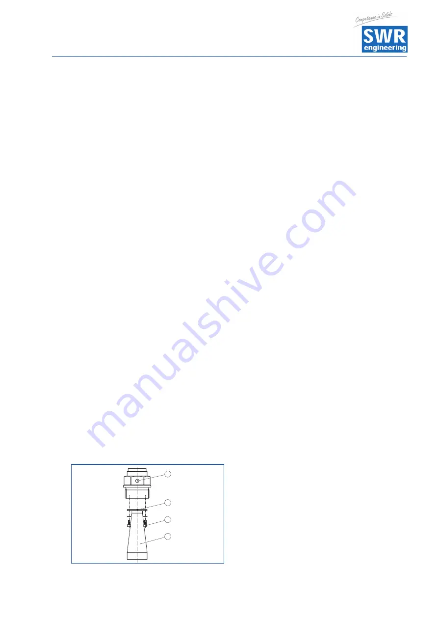
The device is also supplied in versions in which the antenna has a larger diameter than the process
connection (thread or flange). Before installation, therefore, the antenna must be removed from the process
connection. Proceed as follows:
1. Undo the Allen bolts (3) on the antenna base socket using an Allen key (size 3).
2. Remove the antenna (4).
Note:
The plastic cone must not be pulled out of the antenna socket.
3. Push the antenna into the vessel socket from underneath and secure it to prevent it falling.
4. Resecure the antenna to the antenna socket using the Allen bolts; max. tightening torque 2.5 Nm (1.8 lbf ft)
Note:
The radar sensor with a purge air connection or an antenna extension has a mark on the antenna socket. This
marking notch must line up with the marking on the process connection (the marking indicates the position of
the plane polarisation of the radar signal).
3
4
1
2
Fig. 4: Removing the horn antenna
1 Mark for the plane polarisation
2 Mark on the antenna socket
3 Allen bolts on the antenna socket
4 Antenna
r
!


