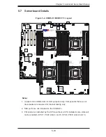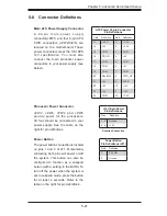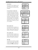
5-20
SUPERSERVER 8047R-TRF+/7RFT+ USER'S MANUAL
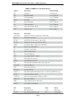
X9QRi-F+/X9QR7-TF+ Quick Reference
Jumper
Description
Default Setting
JBT1
Clear CMOS
See Section 5-9
JPB1
BMC Enable/Disable
Pins 1-2 (Enabled)
JPG1
VGA Enable/Disable
Pins 1-2 (Enabled)
JPRST1
BMC Reset
Off (Normal)
JPS1
SAS Enable/Disable
Pins 1-2 (Enabled)
JPT1
TPM Enable/Disable
Pins 1-2 (Enabled)
JPTG1
GLAN1/GLAN2 Enable/Disable
Pins 1-2 (Enabled)
JWD1
Watch Dog Timer
Pins 1-2 (Reset)
Connector
Description
COM1/COM2
Backplane COM Port1/Front Accessible COM2 Header
FAN1~10
CPU/System Fan Headers
I-SATA 0/1
Intel SB SATA 3.0 Connectors 0/1 (Color: White)
I-SATA 2-5
Intel SB SATA 2.0 Connectors 2~5 (Color: Black)
JIPMB1
4-pin External BMC I
2
C Header (for an IPMI Card)
JD1
Speaker/Power LED Indicator
JF1
Front Panel Control Header
JL1
Chassis Intrusion Header
JOH1
Overheat LED Indicator
JPI
2
C1
Power Supply SMBbus I
2
C Header
JPW1
ATX 24-Pin Power Connector
JPW2~5
12V 8-Pin Power Connectors
JSD1
SATA DOM (Device on Module) Device Power Connector
LAN1/LAN2
Gb Ethernet Ports 1/2
LS2E1
Internal Speaker (Buzzer)
(IPMI) LAN
Dedicated IPMI LAN
SAS0~3, 4~7
SAS (Serial Attached SCSI) Connections 0~3, 4~7 (JS1/2) (for X9QR7-TF+ only)
SWUID
UID (Unit Identi
fi
cation) Switch
T-SGPIO1/2
Serial_Link General Purpose I/O Headers (JP4/JP5)
USB0/1, 2/3
Back Panel USB Ports
USB4
Type A USB Connector for Front Access
USB5/6/7
Front Accessible USB Headers
LED
Description
State
Status
DS1
BMC Heartbeat LED
Green
BMC Normal
LEDUID1
Rear UID (Unit Identi
fi
cation) LED
Blue
Unit Identi
fi
ed


