


6-2
SUPERSERVER 8047R-TRF+/7RFT+ USER'S MANUAL
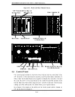
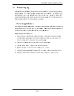
Figure 6-1. Front and Rear Chassis Views
6-2 Control
Panel
The control panel (located on the front of the chassis) must be connected to the
JF1 connector on the serverboard to provide you with system status indications. A
ribbon cable has bundled these wires together to simplify the connection. Connect
the cable from JF1 on the serverboard to the Control Panel PCB (printed circuit
board). Make sure the red wire plugs into pin 1 on both connectors. Pull all excess
cabling out of the air
fl
ow path. The LEDs inform you of system status.
See Chapter 3 for details on the LEDs and the control panel buttons. Details on
JF1 can be found in Chapter 5.
System Reset
Control Panel
Main Power
5.25" PeripheralDrive Bays (3)
SAS/SATA Drives (6)
In Mobile Rack
Ethernet Ports
USB Ports
COM1 Port
Standard Size PCI Slots (6)
(4 on Motherboard)
IPMI LAN
VGA Port
USB Ports (2)
UID
Power Supplies (2)


