75
Chapter 4: Motherboard Connections
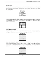
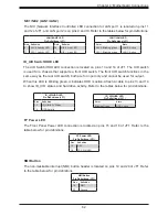
Standby Power
The Standby Power header is located at JSTBY1 on the motherboard. You must have a card
with a Standby Power connector and a cable to use this feature. Refer to the table below
for pin definitions.
Standby Power
Pin Definitions
Pin#
Definition
1
+5V Standby
2
Ground
3
No Connection
Disk-On-Module Power Connector
The Disk-On-Module (DOM) power connectors at JSD1 and JSD2 provide 5V power to a
solid-state DOM storage devices connected to one of the SATA ports. Refer to the table
below for pin definitions.
DOM Power
Pin Definitions
Pin#
Definition
1
5V
2
Ground
3
Ground
Power SMB (I
2
C) Header
The Power System Management Bus (I
2
C) header (JPI2C1) monitors the power supply, fan,
and system temperatures. Refer to the table below for pin definitions.
Power SMB Header
Pin Definitions
Pin#
Definition
1
Clock
2
Data
3
PMBUS_Alert
4
Ground
5
+3.3V
4-pin BMC External I
2
C Header
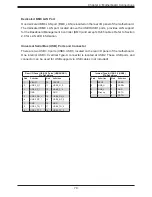
A System Management Bus header for BMC is located at JIPMB1. Connect the appropriate
cable here to use the IPMB I
2
C connection on your system. Refer to the table below for pin
definitions.
External I
2
C Header
Pin Definitions
Pin#
Definition
1
Data
2
Ground
3
Clock
4
No Connection

