


82
Chapter 4: Motherboard Connections
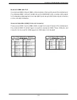
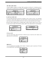
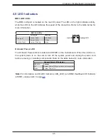
NIC1/NIC2 (LAN1/LAN2)
The NIC (Network Interface Controller) LED connection for LAN port 1 is located on pins 11
and 12 of JF1, and LAN port 2 is on pins 9 and 10. Refer to the tables below for pin definitions.
LAN1/LAN2 LED
Pin Definitions (JF1)
Pin# Definition
Pin# Definitin
9
NIC 2 Activity LED
10
NIC 2 Link LED
11
NIC 1 Activity LED
12
NIC 1 Link LED
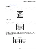
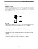
ID_UID Switch/HDD LED
The UID Switch/HDD LED connection is located on pins 13 and 14 of JF1. The UID switch
is used for a chassis that supports a front UID switch. The front UID switch functions in the
same way as the rear UID switch; both are for input only and cannot be used for output.
When this LED is blinking green, it indicates HDD is active. Attach a cable to pins 13 and 14
to show ID_UID status and hard drive activity. Refer to the tables below for pin definitions.
ID_UID/HDD LED
Pin Definitions (JF1)
Pins
Definition
13
ID_UID/3.3V Stdby
14
HDD Activity
ID_UID/HDD LED
Pin Definitions (JF1)
Color
State
Blinking Green
HDD Active
LAN1/LAN2 LED
Pin Definitions (JF1)
Color
State
NIC 2: Blinking green
LAN 2: Active
NIC 1: Blinking green
LAN 1: Active
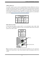
FP Power LED
The Front Panel Power LED connection is located on pins 15 and 16 of JF1. Refer to the
table below for pin definitions.
FP Power LED
Pin Definitions (JF1)
Pins
Definition
15
3.3V
16
FP PWR LED
NMI Button
The non-maskable interrupt (NMI) button header is located on pins 19 and 20 of JF1. Refer
to the table below for pin definitions.
NMI Button
Pin Definitions (JF1)
Pins
Definition
19
NMI
20
Ground


