71
Chapter 4: Motherboard Connections
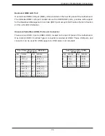
UID (Unit Identifier)/BMC Reset Switch and UID/BMC Reset LED Indicators
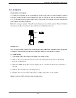
A UID / BMC Reset switch (JUIDB1) is located on the rear side of the motherboard. This
switch has dual functions. It can be used to identify a system unit that is in need of service,
and it can also be used to reset the BMC settings.
When functioning as a BMC reset switch, JUIDB1 will trigger a cold reboot when the user
presses and holds the switch for six seconds. It will also restore the BMC to the manufacturer's
default when the user presses and holds the switch for 12 seconds.
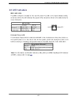
When functioning as a UID LED switch, JUIDB1 will turn both rear UID LED (UID_LED1)
and front UID LED (Pin 7/Pin 8 of JF1) on and off when the user presses the switch on/off.
To achieve these dual purposes, the UID LED/BMC Reset switch works in conjunction with
the BMC Heartbeat LED (LEDM1) and front/rear UID LEDs. Please note that UID can also be
triggered via BMC on the motherboard. For more details on the UID LEDs and BMC LEDs,
refer to the tables below. Also, refer to the BMC User's Guide posted on our website at
for more information on BMC.
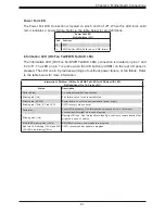
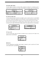
UID/BMC Reset Switch (JUIDB1)
Features & Settings
When Used as a UID LED Switch
When Used as a BMC Reset Switch
Work w/ Rear UID LED (UID_LED1) & Front UID LED (JF1:
Pins 7 & 8)
Work with BMC Heartbeat LED (LEDM1)
Rear UID LED UID_LED1
Blue: Unit identified
BMC Heartbeat LED
LEDM1
Blinking Green: BMC Normal
Front UID LED Pins 7 & 8 (JF1)
Blue: Unit identified
BMC Reset: Press
and hold the switch
(JUIDB1) 6 seconds
LEDM1: Solid Green: during reboot
Press the switch (JUIDB1) to turn on and off both rear
and front UID LED indicators.
Triggering a cold reboot; LED: solid green
on during cold reboot
BMC Reset: Press
and hold the switch
(JUIDB1) 12 seconds
LEDM1: Solid Green: during BMC reset
BMC: Reset to the manufacturer's default;
LED solid on during BMC Reset
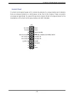
Power Button
(Blue LED_Cathode_UID)
NIC1 (Activity) LED
Reset Button
HDD LED
FP PWR LED
ID_UID/3.3V Stby
Ground
19
Ground
20
1
2
Ground
Power Fail (for LED6)
NIC2 (Link) LED
NMI
3.3V
(Red OH/Fan Fail/PWR Fail for LED5/Blue UID LED)
3.3V
JF1
Red+
Blue+
NIC2 (Activity) LED
NIC1 (Link) LED
Key
Key
3
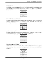
UID/BMC Reset Switch (JUIDB1)
Pin Definitions
Pin#
Definition
1
Ground
2
Ground
3
Button In
4
Button In

