


11
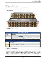
Chapter 1: Introduction
Control Panel Features
Feature
Description
Power button
The main power switch applies or removes primary power from the power supply to the
server but maintains standby power.
UID button/LED
BMC button
The unit identification (UID) button turns on or off the blue light function of the Information
LED and a blue LED on the rear of the chassis.
This button can also be used to reset the BMC. See Chapter 3.
Power LED
Indicates power is being supplied to the system power supply units. This
LED is illuminated when the system is operating normally.
HDD
Indicates activity on the storage drives when flashing.
NIC (LAN1) LED
Indicates network activity on LAN1 when flashing.
NIC (LAN2) LED
Indicates network activity on LAN2 when flashing.
Power Fail LED
Indicates a power supply module has failed.
Information LED
Alerts operator to several states, as noted in the table below.
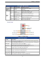
Control Panel
Figure 1-2. Control Panel
Drive Carrier LED Indicators
Color
Blinking Pattern
Behavior for Device
Activity
LED
Blue
Solid On
Idle SAS/NVMe drive installed
Blue
Blinking
I/O activity
Off
Idle SATA drive installed
Status
LED
Red
Solid On
Failure of drive with RSTe support
Red
Blinking at 1 Hz
Rebuild drive with RSTe support
Red
Blinking with two blinks
and one stop at 1 Hz
Hot spare for drive with RSTe support
Red
On for five seconds,
then off
Power on for drive with RSTe support
Red
Blinking at 4 Hz
Identify drive with RSTe support
Green
Solid on
Safe to remove NVMe drive
Amber
Blinking at 1Hz
Do not remove NVMe drive
Power
Power LED
Information LED
UID Button/LED
BMC Reset
HDD
NIC (LAN1) LED
NIC (LAN2) LED
Power Fail LED


