


Chapter 5: Advanced Serverboard Setup
5-25
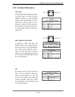
5-10 Onboard Indicators
LAN LEDs
The Ethernet ports (located beside the
VGA port) have two LEDs. On each
Gigabit LAN port, one LED indicates
activity when blinking while the other
LED may be green, amber or off to
indicate the speed of the connection.
See the table on the right for the func-
tions associated with the connection
speed LED.
LAN LED
Connection Speed Indicator
LED Color Defi nition
Off
No connection or 10 Mb/s
Green
100 Mb/s
Amber
1 Gb/s
LE1
An Onboard Power LED is located at
LE1 on the serverboard. When this
LED is lit the system is on. Be sure
to turn off the system and unplug the
power cord before removing or install-
ing components. See the table at right
for more information.
Onboard PWR LED Indicator
LED Color Defi nition
Off
System Off/Power cable
not connected
Green
System On
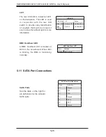
IPMI_Dedicated LAN LEDs
In addition to LAN1 and LAN2, the
X8DTU-LN4F+ has an IPMI_Dedicat-
ed LAN located on the IO backpanel.
The amber LED indicates activity,
while the Link LED may be green,
amber or off to indicate the speed of
the connection. See the tables at right
for more information.
Activity LED
Activity LED
Link LED
Link LED
IPMI LAN Indicator
LED Color Defi nition
Off
No Connection or 10 Mb/s
Green
100 Mb/s
Amber
1 Gb/s
IPMI LAN Activity Indicator
Color Status Defi nition
Amber
Flashing
Active
Summary of Contents for SUPERSERVER 6016T-NTRF4+
Page 1: ...SUPERSERVER 6016T URF4 6016T NTRF4 SUPER USER S MANUAL 1 0a ...
Page 5: ...v Preface Notes ...
Page 21: ...Chapter 2 Server Installation 2 7 Figure 2 3 Installing the Server into a Rack ...
Page 23: ...Chapter 2 Server Installation 2 9 Figure 2 4 Accessing the Inside of the System ...
Page 28: ...3 4 SUPERSERVER 6016T URF4 6016T NTRF4 User s Manual Notes ...
Page 48: ...4 20 SUPERSERVER 6016T URF4 6016T NTRF4 User s Manual Notes ...
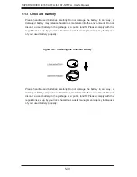
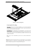
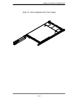
Page 87: ...Chapter 6 Advanced Chassis Setup 6 9 Figure 6 5 Removing Replacing the Power Supply ...
Page 88: ...6 10 SUPERSERVER 6016T URF4 6016T NTRF4 User s Manual Notes ...
Page 116: ...7 28 SUPERSERVER 6016T URF4 6016T NTRF4 User s Manual Notes ...
Page 118: ...A 2 SUPERSERVER 6016T URF4 6016T NTRF4 User s Manual Notes ...


