


5-20
S
UPER
S
ERVER 6016T-URF4+/6016T-NTRF4+ User's Manual
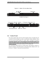
LAN1/2/3/4 (Ethernet Ports)
Four Ethernet ports (designated LAN1,
LAN2, LAN3 and LAN4) are located
beside the VGA port on the I/O back-
plane. A dedicated IPMI LAN port is
also located above USB1. These ports
accept RJ45 type cables.
UID Buttons
There are two Unit Identifi cation (UID)
buttons on the serverboard. The Front
Panel UID Switch connects to pin 13
of JF1. The Rear UID Switch (SW1) is
located next to LAN2. Pushing the UID
switch on the Front Control Panel will
illuminate both the Rear UID and the
Control Panel UID indicators. Push
the either switch again to turn off
both indicators. These UID indicators
provide easy identifi cation of a system
that may be in need of service.
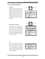
DOM Power Connector
A power connector for SATA DOM
(Disk_On_Module) Devices is located
at JWF1. Connect the appropriate
cable here to provide power support
for your DOM devices.
DOM PWR
Pin Defi nitions
Pin# Defi nition
1
+5V
2
Ground
3
Ground
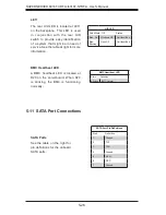
External BMC I
2
C Connectors
Two external BMC (Baseboard Man-
agement Controller) SMBus Power
(I
2
C) connectors are located at JIP-
MB2 and IPMB1. Both JIPMB2 and
IPMB1 are located on the same I
2
C
bus, providing the same support.
Connect one or both connectors for
External BMC I
2
C support.
BMC I
2
C (JIPMB2)
Pin Defi nitions
Pin# Defi nition
1
I
2
C Data
2
Ground
3
I
2
C CLK
BMC I
2
C (IPMB1)
Pin Defi nitions
Pin# Defi nition
1
I
2
C Data
2
Ground
3
I
2
C CLK
4
NC
Summary of Contents for SUPERSERVER 6016T-NTRF4+
Page 1: ...SUPERSERVER 6016T URF4 6016T NTRF4 SUPER USER S MANUAL 1 0a ...
Page 5: ...v Preface Notes ...
Page 21: ...Chapter 2 Server Installation 2 7 Figure 2 3 Installing the Server into a Rack ...
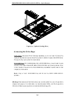
Page 23: ...Chapter 2 Server Installation 2 9 Figure 2 4 Accessing the Inside of the System ...
Page 28: ...3 4 SUPERSERVER 6016T URF4 6016T NTRF4 User s Manual Notes ...
Page 48: ...4 20 SUPERSERVER 6016T URF4 6016T NTRF4 User s Manual Notes ...
Page 87: ...Chapter 6 Advanced Chassis Setup 6 9 Figure 6 5 Removing Replacing the Power Supply ...
Page 88: ...6 10 SUPERSERVER 6016T URF4 6016T NTRF4 User s Manual Notes ...
Page 116: ...7 28 SUPERSERVER 6016T URF4 6016T NTRF4 User s Manual Notes ...
Page 118: ...A 2 SUPERSERVER 6016T URF4 6016T NTRF4 User s Manual Notes ...


