


5-16
S
UPER
S
ERVER 6016T-URF4+/6016T-NTRF4+ User's Manual
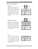
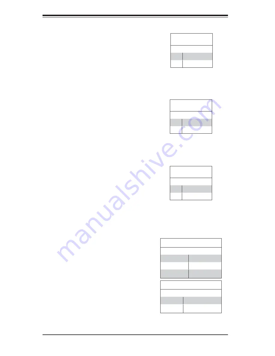
NIC1 LED
The NIC1 (Network Interface Control-
ler) LED connection is located on pins
11 and 12 of JF1. Attach the NIC1
LED cable to display network activity.
Refer to the table on the right for pin
defi nitions.
NIC2 LED
The NIC2 (Network Interface Control-
ler) LED connection is located on
pins 9 and 10 of JF1. Attach the NIC2
LED cable to display network activity.
Refer to the table on the right for pin
defi nitions.
NIC1 LED
Pin Defi nitions (JF1)
Pin# Defi nition
11
Vcc
12
Ground
NIC2 LED
Pin Defi nitions (JF1)
Pin# Defi nition
9
Vcc
10
Ground
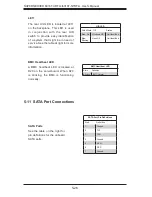
HDD LED
The HDD (IDE Hard Disk Drive) LED
connection is located on pins 13 and
14 of JF1. Attach the IDE hard drive
LED cable to display disk activity.
Refer to the table on the right for pin
defi nitions.
HDD LED
Pin Defi nitions (JF1)
Pin# Defi nition
13
Vcc
14
HD Active
Overheat (OH)/Fan Fail/PWR Fail/
UID LED
Connect an LED to pins 7 and 8 of
JF1 to provide advanced warning of
chassis overheating or fan failure.
These pins also work with the front
UID indicator, which will activate as
either a solid or fl ashing blue LED
depending on whether the LED was
activated via IPMI or the UID button.
Refer to the tables on the right for pin
defi nitions and status indicators.
Red LED Indications
State Indication
Solid
Overheat
Blinking (fast)
Fan Fail
Blinking (slow)
Power Fail
Blue LED Indications
State Indication
Solid
UID (via Button)
Blinking
UID (via IPMI)
Summary of Contents for SUPERSERVER 6016T-NTRF4+
Page 1: ...SUPERSERVER 6016T URF4 6016T NTRF4 SUPER USER S MANUAL 1 0a ...
Page 5: ...v Preface Notes ...
Page 21: ...Chapter 2 Server Installation 2 7 Figure 2 3 Installing the Server into a Rack ...
Page 23: ...Chapter 2 Server Installation 2 9 Figure 2 4 Accessing the Inside of the System ...
Page 28: ...3 4 SUPERSERVER 6016T URF4 6016T NTRF4 User s Manual Notes ...
Page 48: ...4 20 SUPERSERVER 6016T URF4 6016T NTRF4 User s Manual Notes ...
Page 87: ...Chapter 6 Advanced Chassis Setup 6 9 Figure 6 5 Removing Replacing the Power Supply ...
Page 88: ...6 10 SUPERSERVER 6016T URF4 6016T NTRF4 User s Manual Notes ...
Page 116: ...7 28 SUPERSERVER 6016T URF4 6016T NTRF4 User s Manual Notes ...
Page 118: ...A 2 SUPERSERVER 6016T URF4 6016T NTRF4 User s Manual Notes ...


