62
7
Functions of the SD3-A1
The
SD3-A1
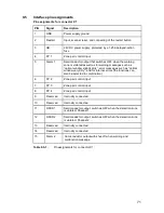
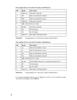
is equipped with the X1 and X2 interfaces. The following functions are
available through them:
7.1 Restart
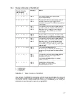
Depending on the operating state, the restart input X1-2 has several functions:
To activate the functions, apply 24V to input X1-2. In the meantime, the safety outputs
OSSD 1 and OSSD 2 are switched OFF; the indicator at the scanner (LED 3) is lit up red.
The duration of the signal must be between 0.12s and 5s.
The restart input X1-2 must be connected to an external, permanently installed button.
X1-2 must not be connected with the remaining controls in order to prevent an unintended
release with a restart pulse under some circumstances.
Force-guided, normally closed contacts can be monitored in the restart circuit (relay
monitoring).
Please note the Chapter 5 (Information for Planning and Mounting) and 9.1 (Electrical
power supply).
7.2 Channels
for
zone pair changeovers, FP 1 to FP 4
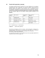
To activate the zone pairs, apply 24V (see Chapter 9.1) to the following inputs:
The following points also apply for the switchover:
If these points are not observed the laser scanner will fail within 40ms and will show this
with the additional 2Hz flashing of the green LED 1.
x
Enables the restart interlock following the interruption of a detection zone
x
Enables the start interlock following a system start
x
Restarts after a device error has been eliminated
x
Recognizes a defined enable signal
after a device error
after a detection zone interruption for enabling the restart interlock
x
X1-4 (FP 1)
x
X1-6 (FP 2)
x
X1-7 (FP 3)
x
X1-8 (FP 4)
x
The switchover must be made within 40ms, i.e. after 40ms one of the input
connections shown in Table 6.1-1 must be valid and provided stable. During the
switchover time the old zone pair is monitored; the new one after max. 80ms.
x
The switchover process executed by the control unit must concur with the laser
scanner’s configuration, which was set beforehand with
SD3SOFT
.
Summary of Contents for SD3-A1
Page 1: ......
Page 12: ...12...
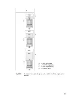
Page 40: ...40 Fig 5 4 5 Considering the maximum measurement distance when safeguarding an area...
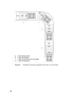
Page 60: ...60 Fig 6 2 1 Example of a zone pair changeover for an AGV on a curved route...
Page 61: ...61 Fig 6 2 2 Example of zone pair changeover with combined with reducing speed of the AGV...
Page 101: ...101 13 13 Dimensional drawings of the SD3 A1...
Page 102: ...102 13 14 Dimensional drawings of the mounting system...
Page 106: ......

