background image

99

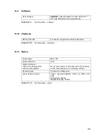
13.9   Software 

Table 13.9-1: 

Technical data – software

13.10 Interfaces

Table 13.10-1: 

Technical data – interfaces 

13.11 Optics 

Table 13.11-1: 

Technical data – optics 

User software 

SD3SOFT

 under Windows

®

 95 / 98 / 2000 / NT

®

 / 

XP

®

 with safe protocol for programming 

RS-232, RS-422 

For device configuration and data exchange 

Angle range 

Max. 190° 

Angle resolution 

0.36° 

Lateral tolerance 
without mounting system 
with mounting system 

±0.18° (with respect to the back wall of the housing) 

±0.22° (with respect to the mounting surface) 

Scanning rate 

25 scans/s or 40ms/scan 

Laser protection class 

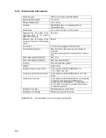
Class 1, as per EN 60825-1: 1994 + A1: 2002 + A2: 
2001
Wavelength: 905nm 
Repeat frequency: 25kHz 

Summary of Contents for SD3-A1

Page 1: ......

Page 2: ...s The instruction manual connection and operation and the instruction manual software operation must be kept in a safe place They must be available during the entire period when the SD3 A1 is in use D...

Page 3: ...transporter trolleys against collisions 22 4 6 Guarding the sides on AGVs 23 4 7 Other possible applications 24 5 Information for Planning and Mounting 25 5 1 Attachment and dimensions 26 5 2 Installi...

Page 4: ...7 2 Channels for zone pair changeovers FP 1 to FP 4 62 7 3 Alarm 1 X1 5 63 7 4 Alarm 2 X1 15 63 7 5 OSSD 1 X1 12 and OSSD 2 X1 11 64 7 6 Data communication 64 8 Integrating the SD3 A1 into Machine Co...

Page 5: ...87 11 7 1 General information 87 11 7 2 Initial measurement of the new optical window 89 11 7 3 Procedure when using the SD3SOFT user software version 1 09 or later 90 11 8 Cleaning 91 11 8 1 Cleanin...

Page 6: ...6 1 Approvals 1 1 Approval and declaration of EC conformity EC type examination in accordance with DIN EN 61496 1 and IEC 61496 3 TUV PRODUCT SERVICE GMBH IQSE Ridlerstr 65 80339 Munich...

Page 7: ...lection EDM External Device Monitoring Monitoring of external control parts relay monitoring ESPE Electro Sensitive Protecting Equipment BWS in German N O Normal open contact OSSD Output Signal Switch...

Page 8: ...related parts of control systems Part 1 General principles for design ISO 13855 Safety of machinery The positioning of protective equipment in respect of approach speeds of parts of the human body B2...

Page 9: ...a person or an object the reflected light is received and evaluated by the SD3 A1 The scanner calculates the precise coordinates of the person or object based on the travel time of the reflected ligh...

Page 10: ...urface by a rotating mirror in such a way that a light pulse is triggered in each of the angle segments within 40ms scanning rate 25 scans s Fig 2 1 2 Functional principle of the SD3 A1 The SD3 A1 can...

Page 11: ...sport vehicles Due to its wide range of measurement and its non contact electro sensitive measurement principle the SD3 A1 can be effectively used as a protective device for virtually any application...

Page 12: ...12...

Page 13: ...for questions related to safety In general the following usage requirements must be observed x If the scanner is enclosed in a protective housing additional window material such as plastic or glass mu...

Page 14: ...ion zone configurations Familiarity with the safety notes in this instruction manual connection and operation and in the instruction manual software operation for the SD3SOFT program constitutes part...

Page 15: ...ted inside the danger areas x There must be no unmonitored zones inside the danger areas x There must be no possibility for direct access to the danger area that shortens the necessary safety distance...

Page 16: ...angle range stated in the technical specifications Chapter 13 11 x Needle shaped detection zone contours are not permitted since they do not ensure any protective effect For additional information ple...

Page 17: ...made to an AGV x In the event that there is insufficient room available to allow the full dimensions of a detection zone for example because of the position of the scanner additional safety measures...

Page 18: ...distance SAB of 500mm to the side of the vehicle on both sides A one sided minimum safety distance is admissible in certain exceptional cases The specifications of DIN EN 1525 must be complied with x...

Page 19: ...on the geometrical shape of the detection zone The aim is to prevent people from entering the danger zone or reaching the danger point with their upper and or lower extremities at the same time withou...

Page 20: ...nd fence against inadvertent misadjustment and manipulation the detection zones of the SD3 A1 must be defined on the basis of a reference boundary In this operating mode the scanner will use the polle...

Page 21: ...able in such a situation to guarantee flexible safety conditions in the workplace This may be combined with alternation of the detection zones In order to safeguard the protective equipment laser scan...

Page 22: ...ety zone The vehicles can move faster and down times are reduced to the necessary minimum Fig 4 4 1 Safeguarding an automatic guided vehicle Please comply with the safety notes in Chapter 3 For an exa...

Page 23: ...ctors such as additions in the direction of travel for tolerances in the measurement value and reduced braking power due to wear and tear must be taken into consideration 4 6 Guarding the sides on AGV...

Page 24: ...e side guarding configuration on AGVs can be found in Chapter 5 7 9 and 5 7 10 4 7 Other possible applications x Object and contour measurement x Logistics counting measuring controlling x Projection...

Page 25: ...art of the detection zone boundary these should be safeguarded e g by protective grids in order to prevent people standing in them from being able to suddenly enter the detection zone This point must...

Page 26: ...n 5 2 2 are implemented then the SD3 A1 response time set and shown in the configuration and diagnosis software SD3SOFT is extended by 40ms This extension in the response time must be taken into accou...

Page 27: ...nstallation on the basis of the MS SD3 1 mounting system makes precise adjustment significantly easier Installation with height offset or a crossed alignment also prevents interference from beam refle...

Page 28: ...s in mm Graphic input A separate dialog within the user program SD3SOFT allows the basic contours of the detection zone to be entered The contours can be adapted infinitely to the desired size of the...

Page 29: ...able range for an object with a diameter of 150mm is 15m Both of these figures assume a reflectance factor of 20 a Detection zone b Warning zone c Measurement field Fig 5 3 1 Detecting objects in the...

Page 30: ...ating mirror 5 3 5 The SD3 A1 is equipped with a selectable dust algorithm to ensure optimum freedom from interference The following detection zone additions must be taken into account Activation and...

Page 31: ...ger zone to be monitored completely If a restart button is being used make certain that the entire detection zone area can be viewed by the person pressing the button It must not be possible to activa...

Page 32: ...e admissible height range of the SD3 A1 scanning plane lies between 0mm presettings leg detection and 1 000mm above the base level If the application requires a scanning plane higher than 300mm or if...

Page 33: ...h of the undercut is reduced by the depth value of the recess If the mounting system is being used the necessary dimensions of the undercut depth must be increased accordingly see Chapter 13 13 and 13...

Page 34: ...the machine additional safety measures must be taken The effectiveness of the detection zones can be optimized by changing the depth at which the scanner is installed or by adjusting the angle range...

Page 35: ...external scanner mounting without an undercut If the machine contour runs parallel to the 90 beam of the laterally placed SD3 A1 the distance between the detection zone boundary and the machine may no...

Page 36: ...ing to the following formula ZUMIN Z 83mm d ZUMIN Depth of the undercut in mm Z Required detection zone additions in mm d Resolution of the scanner d 70mm This is possible since it is absolutely certa...

Page 37: ...Manual restart the required enable from the startup restart button affects all detection zones and is independent of any detection zone changeover If the current detection zone is manually enabled thi...

Page 38: ...e system response time and braking time until standstill in s C Safety related constant to consider entry into the danger zone before the protective device is triggered in mm CMIN Minimum value of the...

Page 39: ...including system and application specific additions in mm K Approach speed of a person or a person s body parts 1 600mm s in mm s TSCAN Response time of the scanner in s TMACH Response time of the mac...

Page 40: ...40 Fig 5 4 5 Considering the maximum measurement distance when safeguarding an area...

Page 41: ...0mm s constant Response time of the SD3 A1 adjustable TSCAN 0 08s Response time of the machine or system TMACH 0 1s Stopping time or lag time of the machine or system TLAG 0 5s time for braking the da...

Page 42: ...AX 3 901mm 5 4 8 5 This example is based on the following application data If the scanner is mounted across from the machine see Fig 5 4 4 the undercut dimension can be reduced by d 70mm Fig 5 4 6 The...

Page 43: ...of the detection zone must be defined in such a way that no gaps measuring more than 150mm can arise 5 5 3 To safeguard the protective equipment against inadvertent misadjustment or manipulation the d...

Page 44: ...rence boundary Fig 5 5 1 Access protection by passage monitoring with system check of a reference boundary S Safety distance in mm K Approach velocity in mm s Here 1 600mm s T Overall time of delay in...

Page 45: ...the machine It is best if the laser scanner is firmly installed above the danger zone in such a way that it cannot be manipulated The health and safety officer must ensure that the installation posit...

Page 46: ...please also have regard to the illustrations given in this chapter S Safety distance in mm K Approach velocity in mm s At a close distance of 500mm a velocity of 2 000mm s should be assumed If the ca...

Page 47: ...This can be very effectively managed by screening the sides of the danger zone The reference boundary should be defined with reference to the non moving parts of the screen arrangement The detection z...

Page 48: ...scanner and hence the beam axis must be aligned horizontally in order to achieve a consistent scanning height Please comply with the safety notes in Chapter 3 7 5 7 4 As a rule the scanner should be...

Page 49: ...ection zone of a SD3 A1 mounted on an AGV does not cover the entire front of the vehicle you can prevent the creation of unmonitored zones by changing the installation depth of the scanner or by adjus...

Page 50: ...ctional limitations additional safety measures such as mechanical cover panels switch strips or bumpers must be implemented Please comply with the safety notes in Chapter 3 7 Fig 5 7 2 Three possibili...

Page 51: ...ea Without information from the AGV manufacturer take into account the wear and tear on the brakes by adding an addition LSTOP of at least 10 of the braking distance as long as this is not already inc...

Page 52: ...are included they will not be removed Safety notes Automatic startup restart must only be used in cases where there is absolutely no possibility that the effective detection zone could be entered or...

Page 53: ...wear and tear on the brakes ZTOT Total of the system and application specific additions in the direction of travel in mm ZTOT ZSM ZREFL ZAFLR ZAU ZSM Scanner measurement error in mm ZREFL Addition of...

Page 54: ...g 5 7 4 Considering the maximum measurement distance for safeguarding AGVs In accordance with DIN EN 1525 a minimum safety distance of 0 5m width between the vehicle and its environment must be mainta...

Page 55: ...ion of the width of the danger zone results in the maximum distance to be monitored SBDIFF 1 400mm 83mm 1 483mm SMAX Largest width of the danger zone from the axis of the rotating mirror GBDIFF 1 400m...

Page 56: ...r scanner resolution of 150mm is required to detect an entire person This safety relevant setting is automatically set in the SD3SOFT configuration and diagnostics software with selection of the perso...

Page 57: ...t in Chapter 9 5 and the safety notes in Chapter 3 6 1 Sequence of zone pair switchovers The SD3 A1 safety laser scanner has eight detection warning zones Switchover between these zone pairs is possib...

Page 58: ...Zone pair 7 is active 8 0 1 1 1 Zone pair 8 is active The following points also apply for the switchover If these points are not observed the laser scanner will fail within 40ms and will show this wit...

Page 59: ...n manual software operation for the SD3SOFT FP 1 detection zone 1 warning zone Practical AGV application If the AGV is controlled by a PLC for instance which corresponds to Category 3 or higher accord...

Page 60: ...60 Fig 6 2 1 Example of a zone pair changeover for an AGV on a curved route...

Page 61: ...61 Fig 6 2 2 Example of zone pair changeover with combined with reducing speed of the AGV...

Page 62: ...upply 7 2 Channels for zone pair changeovers FP 1 to FP 4 To activate the zone pairs apply 24V see Chapter 9 1 to the following inputs The following points also apply for the switchover If these point...

Page 63: ...by the continuously lit LED 2 in the indicator field of the scanner x Warning state For instance the system may detect a slight dirt buildup on the optical window To signal this state LED 5 on the sca...

Page 64: ...itself to the appropriate transfer type and baud rate The interface X2 is used for Guard operation is only permitted with the PC cable X2 or dummy connected screwed ON This also applies for transport...

Page 65: ...ir changeover and restart interlock example Relays K1 and K2 must have forced contacts They are operated directly at the two failsafe semiconductor outputs OSSD 1 X1 12 and OSSD 2 X1 11 Relay K3 has a...

Page 66: ...SD 2 X1 11 A suitable mechanism must be provided for extinguishing sparks Please note that doing this will cause the switching time to be extended Channels x and y must be integrated for Category 3 in...

Page 67: ...ust be equipped with positively guided contacts A suitable mechanism must be provided for extinguishing sparks Please note that doing this will cause the switching time to be extended Please refer to...

Page 68: ...sample connection are controlled directly by the PLC The changeover of 4 zone pairs is achieved by way of the inputs X1 4 FP 1 X1 6 FP 2 X1 7 FP 3 and X1 8 FP 4 For applications in which the scanner m...

Page 69: ...d input and output circuits must be provided by a power supply unit with protective isolation from a safety transformer according to IEC 742 or comparable this also applies for the use of battery char...

Page 70: ...es for machines This minimizes the effects of inductive interference factors from motors carrying high current In addition the cables should be laid so that they cannot be damaged e g by being crushed...

Page 71: ...as optical window slightly dirty error messages such as optical window very dirty and for internal errors the functions can also be selected in combination 6 FP 2 Zone pair control input 7 FP 3 Zone...

Page 72: ...on 1 Reserved Internally connected 2 TxD Data communication transmit 3 RxD Data communication receive 4 Reserved Internally connected 5 GND shield Ground shield 6 RS 232 Internally connected 7 N C Do...

Page 73: ...1 x RS 232 interface cable 1 1 without cross connection x Shielded control cable for the power supply and for activating a zone pair x Power supply that meets the requirements specified in Chapter 9 1...

Page 74: ...the SD3SOFT Please observe Chapter 11 Maintenance and Testing x When the connection between the SD3 A1 and the PC was successful you can enter the appropriate password and then change the parameters...

Page 75: ...3 SD3 A1 status indicator There are five LEDs located on the front of the scanner behind the cover with the matte finish These LEDs indicate the status of the SD3 A1 Fig 10 3 1 The SD3 A1 status indi...

Page 76: ...ree Fault input zone pairs Light flashing at 2Hz 2 Yellow 3 Red OSSD outputs are switched OFF 4 Green OSSD outputs are switched ON 5 Yellow ok STOP ok Configuration conflict Light flashing at 4Hz Warn...

Page 77: ...ction is active measurement operation without a violation of the activated detection zone Violation of the activated warning zone The OSSDs are switched active high 0 1 1 0 LED 2 LED 3 Violation of th...

Page 78: ...e All procedures and specifications of the first startup apply here A technical expert should look at the device If the ConfigPlug is used with integrated configuration memory the SD3 A1 reads the sav...

Page 79: ...d be restored Please see the chapter entitled Set default configuration values in the instruction manual software operation for the SD3SOFT x Check in accordance with the guidelines cited above using...

Page 80: ...erformed by responsible operating personnel The SD3 A1 is a safety oriented laser scanner of Category 3 It is extremely important however to check the effectiveness of the detection zone with the test...

Page 81: ...es or gaps in safety e g changes in access possibilities or changes in the surrounding area Yes No 6 If the protective function of the SD3 A1 is present for all required monitoring cases e g testing t...

Page 82: ...6 If the protective function of the SD3 A1 is present for all required monitoring cases e g testing the switch off function with a test piece along the detection zone contour the LED 3 for SD3 A1 mus...

Page 83: ...l system match the circuit diagrams Yes No 7 Was the safety distance calculated according to the applicable formulas for safeguarding danger areas and is this minimum distance observed between the det...

Page 84: ...ork in all necessary operating modes and during the entire motion of the machine that is causing a hazard Yes No 18 Is the motion causing the hazard stopped when electrical power to the SD3 A1 is disc...

Page 85: ...tion of the SD3 A1 to the vehicle control system match the circuit diagrams Yes No 7 Has the safety distance for safeguarding automatic guided vehicles AGV been calculated and observed according to ap...

Page 86: ...ation of the start restart button necessary to reset the vehicle after the power is restored Yes No 15 Are all test and parameter inaccessible to unauthorized personnel Yes No 16 Is an identifying sig...

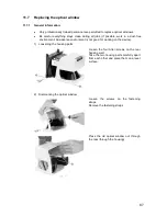
Page 87: ...om each other and place them on a level surface Loosen the screws on the fastening straps Remove the fastening straps Press the old optical window out through the rear through the housing x Only profe...

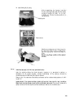
Page 88: ...s and carefully insert it in the correct position pressing the optical window together slightly as you do so Make certain the rubber seal is not damaged Make certain it is in the groove in the housing...

Page 89: ...lean and in new condition Dirty and scratched panes must not be calibrated and used They would represent a safety risk since the laser light would be weakened under some circumstances When assembling...

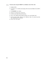
Page 90: ...ed and X2 RS 232 cable 1 1 3 Start SD3SOFT user software 4 Select the Authorized user access level 5 Confirm the echo data shown by the scanner 6 Click on the Calibrate optical window monitoring icon...

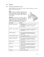
Page 91: ...pe clean with a cleaning cloth wiping in one direction only Particles loose not abrasive Suction off with no contact or blow off with oil free air Wipe clean with a cleaning cloth wiping in one direct...

Page 92: ...uestion Generally this is a quick process Fig 11 8 1 Cleaning the optical window Sharp cleaning materials and cloths that scratch must never be used Fig 11 8 2 Cleaning diffusing light panes Note Dirt...

Page 93: ...connector complete 15 pin interface X1 x SD3 A1 connector complete 9 pin interface X2 x Instruction manual connection and operation for SD3 A1 instruction manual software operation for SD3SOFT Configu...

Page 94: ...ConfigPlug ready made at scanner side 10m angled SD3 RS232 C3 SD3 A1 PC cable RS 232 ready made on both sides 3m SD3 RS232 C5 SD3 A1 PC cable RS 232 ready made on both sides 5m SD3 RS232 C10 SD3 A1 PC...

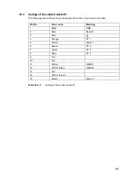
Page 95: ...he 15 pin connector cable Table 12 3 1 Coding of the control cable X1 Pin No Color code Meaning 1 Black GND 2 Blue Restart 3 Red UB 4 Orange FP 1 5 Yellow Alarm 1 6 Green FP 2 7 Violet FP 3 8 Gray FP...

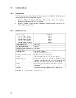
Page 96: ...0mm at a resolution of 40mm at a resolution of 50mm at a resolution of 70mm at a resolution of 150mm 1 60m 2 20m 2 80m 4 00m 4 00m Reflectance factor Min 1 8 Min adjustable range 200mm Detection range...

Page 97: ...surfaces such as certain metals or ceramics are present in the scanning plane 0mm more than 1 2m behind the detection zone line 110mm in the detection zone or up to 1 2m behind detection zone line De...

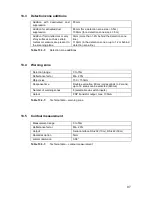
Page 98: ...Non fused ground conductor Connection not allowed Restart reset For connecting a command device for operating mode with restart interlock and or device reset 24V DC insulated by photocoupler Zone pai...

Page 99: ...otocol for programming RS 232 RS 422 For device configuration and data exchange Angle range Max 190 Angle resolution 0 36 Lateral tolerance without mounting system with mounting system 0 18 with respe...

Page 100: ...X1 Max 50m at a cable cross section of 0 5mm2 shielded Connect shield with PE to the electronics cabinet only Data cable length X2 RS 232 Max 10m Data cable length X2 RS 422 Max 50m twisted pair Housi...

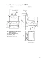
Page 101: ...101 13 13 Dimensional drawings of the SD3 A1...

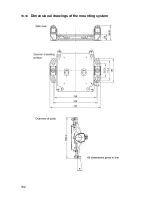
Page 102: ...102 13 14 Dimensional drawings of the mounting system...

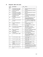
Page 103: ...emory cannot be read internal fault 805 Processing of the commands to the event memory 6 Event memory cannot be transferred Data transmission error on interface X2 1002 Motor control during initializa...

Page 104: ...fault 1907 Test of the external watchdog 4 Event detected by watchdog watchdog switched OFF motor speed deviation scanner housing may be rotating 1907 Test of the external watchdog 7 Event detected b...

Page 105: ...the requirement programmed in the scanner 2800 Processing of inputs for detection zone changeover 4 More than 2 detection zones selected during operation 2800 Processing of inputs for detection zone...

Page 106: ......
Reviews: