background image

4-18

    Sun Java Workstation W1100z and W2100z User Guide


• January 

2005


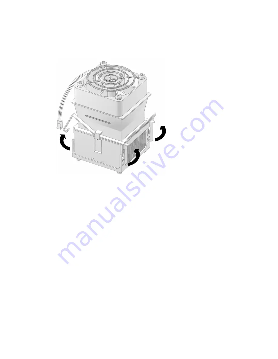
310-0020-01: Unlatch the retaining clips on each side of the heatsink/fan assembly 
(see 

FIGURE


4-10

).

FIGURE


4-10 

Unfastening the Heatsink/Fan Assembly Retaining Clips (

310-0020-01

)

3. Twist the heatsink/fan assembly to the right or the left, in order to break the seal 

with the thermal grease. 

Summary of Contents for W1100z

Page 1: ...Sun Microsystems Inc www sun com Submit comments about this document at http www sun com hwdocs feedback Sun Java Workstation W1100z and W2100z User Guide Part No 817 6585 12 January 2005 Revision A ...

Page 2: ...yright 2005 Sun Microsystems Inc 4150 Network Circle Santa Clara Californie 95054 Etats Unis Tous droits réservés Sun Microsystems Inc a les droits de propriété intellectuels relatants à la technologie qui est décrit dans ce document En particulier et sans la limitation ces droits de propriété intellectuels peuvent inclure un ou plus des brevets américains énumérés à http www sun com patents et un...

Page 3: ...4 1 2 3 Java Desktop System 1 4 1 3 Hardware System Overview 1 5 1 3 1 External Components 1 5 1 3 2 Internal Components 1 7 1 4 Powering the Workstation On and Off 1 9 1 4 1 Powering On the Workstation 1 9 1 4 2 Powering Off the Workstation 1 10 1 4 3 Power Interruptions 1 10 1 5 Customer Orderable Components 1 11 2 Troubleshooting 2 1 2 1 Visual Inspection 2 2 2 1 1 Performing an External Visual...

Page 4: ...tions on a Hard Disk 3 12 3 6 2 Adding a Diagnostic Partition to the First Bootable Disk 3 13 3 6 3 Creating a Log File on the Diagnostic Partition 3 14 3 6 4 Accessing the Diagnostic Partition Under Red Hat Linux 3 15 3 6 5 Accessing the Diagnostic Partition Under Solaris x86 3 16 3 6 6 Accessing the Diagnostic Partition Under Windows 3 17 3 7 Show Results Summary 3 17 3 8 Print Results Report 3 ...

Page 5: ...Replacing or Adding DIMMs 4 28 4 5 6 Installing a PCI or AGP Card 4 31 4 5 7 Replacing the System Battery 4 38 4 5 8 Replacing the System Fan 4 39 4 5 9 Replacing the Power Supply 4 41 4 5 10 Replacing the USB Audio Card Assembly 4 42 4 5 11 Replacing the Operator s Panel 4 43 4 5 12 Replacing System Cables 4 44 4 5 13 Replacing the Mezzanine Card 4 47 4 5 14 Replacing the Extender Card 4 49 4 5 1...

Page 6: ...vi Sun Java Workstation W1100z and W2100z User Guide January 2005 ...

Page 7: ...rs network administrators or service technicians who have knowledge of workstation hardware and software How This Book is Organized Chapter 1 contains an overview of the Sun Java Workstation W1100z and W2100 Chapter 2 contains information on troubleshooting the workstations Chapter 3 contains information on diagnostics Chapter 4 contains information on removing and replacing components Appendix A ...

Page 8: ...der My Online Account on the right Typeface The settings on your browser might differ from these settings Meaning Examples AaBbCc123 The names of commands files and directories on screen computer output Edit your login file Use ls a to list all files You have mail AaBbCc123 What you type when contrasted with on screen computer output su Password AaBbCc123 Book titles new words or terms words to be...

Page 9: ...om the Documentation link at http www sun com w1100z http www sun com w2100z Application Title Part Number System setup information Sun Java Workstation W1100z and W2100z Workstations Setup Poster 817 6583 xx Installation information Sun Java Workstation W1100z and W2100z Getting Started Guide 817 6584 xx Safety Information Sun Java Workstation W1100z and W2100z Safely and Compliance Guide 817 658...

Page 10: ...nderstand the steps we take to respect your privacy Warranty For specific details regarding your warranty visit http www sun com service support warranty index html Sun Welcomes Your Comments Sun is interested in improving its documentation and welcomes your comments and suggestions You can submit your comments by going to http www sun com hwdocs feedback Please include the title and part number o...

Page 11: ...GB hard drives or up to four 73 GB Ultra 320 SCSI hard drives The Sun Java Workstation W1100z and W2100z are equipped with one AGP8x slot for high end graphics cards and one 133 MHz and four 100 MHz PCI X slots The workstation also includes a Gigabit Ethernet interface two IEEE 1394 interfaces five USB 2 0 interfaces and industry standard audio interfaces The following sections are included in thi...

Page 12: ...e For the two processor configuration the system supports eight slots and a maximum memory capacity of 16 GB Media storage CD RW DVD ROM and DVD RW drives Hard disk drives Up to four USCSI 320 73 GB drives or up to two PATA100 80 GB drives Hard drive types cannot be combined Power supply 550W PSU Network I O Onboard Broadcom BCM5703ci 10 100 1000BASE T Gigabit Ethernet controller PCI I O Five PCI ...

Page 13: ...a sets that come with the operating system software The Solaris 9 x86 HW Operating Environment 4 04 or latest version is included on a DVD shipped with the Sun Java Workstation W1100z or W2100z Ensure that you use the version of Solaris 9 x86 that comes with the workstation because it includes the drivers necessary for running Solaris 9 on the Sun Java Workstation W1100z or Sun W2100z If you want ...

Page 14: ...des various diagnostics testing options for the Sun Java Workstation W1100z and W2100z See Diagnostics on page 3 1 for more information 1 2 3 Java Desktop System The Java Desktop System might be preinstalled on your system If your Sun Java Workstation W1100z or W2100z did not come with the Java Desktop System preinstalled you can download it from the following site http wwws sun com software javad...

Page 15: ...eatures of your Sun Java Workstation W1100z or W2100z 1 3 1 External Components 1 3 1 1 Front and Rear Panels FIGURE 1 1 illustrates the front panel of the Sun Java Workstation W1100z and W2100z FIGURE 1 1 Front Panel CD DVD ROM drive Power button Hard Disk Drive Activity LED System Fault LED USB 2 0 connectors IEEE 1394 connector Microphone in Jack Line out Jack ...

Page 16: ... lit when there is system hard drive activity System Fault This LED blinks when a severe system fault such as an over voltage condition or an upper temperature limit is detected If this LED is lit view the DMI event log in the BIOS setup tool for more information on the fault condition AC Power connector Unused PCI X 100 Mhz PCI X 100 Mhz PCI X 100 Mhz PCI X 100 Mhz PCI X 133 Mhz AGP 8X Parallel c...

Page 17: ...n Java Workstation W1100z with a one processor 1P configuration FIGURE 1 3 Sun Java Workstation W1100z System Components Motherboard Memory Banks DIMMs 1 4 Retaining Lever for CD DVD Drive Retaining Lever for 5 25 Devices optional Drive Cage CPU 0 Power Supply System Fan PCI X 100 MHz PCI X 100 MHz PCI X 133 MHz PCI X 100 MHz AGP 8X PCI X 100 MHz Extender Card ...

Page 18: ...nfiguration FIGURE 1 4 Sun Java Workstation W2100z System Components Motherboard Memory Banks DIMMs 1 4 Retaining Lever for CD DVD Drive Retaining Lever for 5 25 Devices optional Drive Cage CPU 0 Power Supply System Fan Extender Card Mezzanine Card with CPU 1 optional Mezzanine Card Memory Banks DIMMs 5 8 PCI X 100 MHz PCI X 100 MHz PCI X 133 MHz PCI X 100 MHz AGP 8X PCI X 100 MHz ...

Page 19: ...r on the workstation Follow these steps to power up the workstation 1 Turn on power to the monitor and to all external devices 2 Press and release the workstation Power button on the front panel FIGURE 1 1 3 After several seconds verify that the platform power LED on the Power button is lit The platform power LED on the Power button lights after the workstation begins the internal booting process ...

Page 20: ...n Note Use one of the first two options whenever possible to avoid data loss If the workstation power does not shut off with one of the first two options press and hold the Power button for approximately 4 seconds This shuts down the power to the workstation but does not initiate an orderly shutdown of the system This method could result in data loss If the proceeding options fail to power off the...

Page 21: ... for the Sun Java Workstation W2100z and some are available for either system Contact your local Sun sales representative for more information For the most up to date component information see the components list on one of the following web sites http sunsolve sun com handbook_pub Systems W1100z or http sunsolve sun com handbook_pub Systems W2100z Note The Sun Java Workstation W1100z and W2100z ar...

Page 22: ...1 12 Sun Java Workstation W1100z and W2100z User Guide January 2005 ...

Page 23: ...ssessed the problem and noted your current configuration and environment you can choose from several ways to troubleshoot your workstation Visually inspect your system as described in Section 2 1 Visual Inspection on page 2 2 View the troubleshooting procedures in Section 2 2 Troubleshooting Procedures on page 2 3 to see if any of them solve the problem Execute diagnostics test as described in Cha...

Page 24: ...connected to the system the monitor and peripherals and check their power sources 3 Inspect connections to any attached devices including network cables keyboard monitor and mouse as well as any devices attached to the serial port 2 1 2 Performing an Internal Visual Inspection 1 Shut down the operating system if necessary and turn off the platform power on the front of the workstation 2 Turn off t...

Page 25: ...t Make sure the power cable is connected correctly Make sure that the wall outlet has power Test it by plugging in another device Workstation does not power off when the front panel power button is pressed Try all of the power off options shown in Section 1 4 2 Powering Off the Workstation on page 1 10 If the workstation still does not power off disconnect the power cable from the rear of the chas...

Page 26: ...y in its connector Are the internal cables properly connected to the video card External device is not working Check the documentation that came with the device to see if any device drivers need to be installed Ensure that the cables for the external device are firmly connected and that the pins in the cable and connector are not bent Power off the system re attach the external device and power on...

Page 27: ...p docs sun com documentation Discussion and troubleshooting forums http supportforum sun com Support diagnostic tools and alerts for all Sun products http www sun com bigadmin SunSolveSM web site Contains links to software patches Lists some system specifications troubleshooting and maintenance information and other tools http www sunsolve sun com handbook_pub SunServiceSM support phone numbers 1 ...

Page 28: ...2 6 Sun Java Workstation W1100z and W2100z User Guide January 2005 ...

Page 29: ...ollowing sections are included in this chapter Section 3 1 Diagnostics Main Menu on page 3 2 Section 3 2 System Information Menu on page 3 3 Section 3 3 Advanced Diagnostics on page 3 4 Section 3 4 Immediate Burn In Testing on page 3 8 Section 3 5 Deferred Burn In Testing on page 3 10 Section 3 6 Create Diagnostic Partition on page 3 11 Section 3 7 Show Results Summary on page 3 17 Section 3 8 Pri...

Page 30: ...un the Hardware Diagnostics Software The system information loads then the Diagnostics Main Menu opens and the following menu options are displayed System Information Menu Advanced Diagnostics Tests Immediate Burn in Testing Deferred Burn in Testing Create Diagnostic Partition Show Results Summary Print Results Report About PC CHECK Exit to DOS Note Using the diagnostics menu and options is simila...

Page 31: ...stem event log memory array memory devices memory device mapped addresses and system boot PCI Bus Information Similar to the System Management Information section this section includes details about specific devices from pci config space within the system IDE Bus Information Shows the master slave devices on the primary and secondary IDE controllers PCMCIA CardBus Info Not relevant to Sun Java Wor...

Page 32: ...out the processor and includes a Processor Tests menu to test the processor on the system Memory Details information about the memory and includes a Memory Tests menu to test the memory on the system Also lists each type of memory in the system such as system cache or video memory Motherboard Details information about the motherboard and includes a Motherboard Tests menu to test the motherboard on...

Page 33: ...et supported on the Sun W1100 and W2100 workstations USB Details information about the USB devices on the system and includes an USB Tests menu to test the USB FireWire Details information about FireWire devices and includes a FireWire tests menu SCSI Preforms SCSI register controller tests Network Performs network register controller tests Keyboard Includes a Keyboard Test menu with options for p...

Page 34: ... Error Log Utilities Menu Exit The Media Test options include the Read Test the Read Verify Test the Non Destructive Write Test and the Destructive Write Test These tests are relevant to testing the media associated with the hard drive hardware such as the physical disk Caution Running the Destructive Write Test destroys any data that is on the disk Video Details information about the video card I...

Page 35: ...st Settings include the following Media Test Settings Enables you to choose the test time duration the percentage of the hard disk to test and the sectors to be tested on the hard disk Device Test Settings Enables you to select the test time durations of the devices and the test level Number of Retries Enables you to select the number of times to retry testing a device before terminating the test ...

Page 36: ...em It can take up to one hour and twenty minutes full tst Performs a complete test on all components to determine the operating status of your system This test can take several hours depending upon your system configuration Tip Each of these scripts test the operating status of your entire system If you want to test only a certain percentage of your system s hard drives refer to the Section 3 3 1 ...

Page 37: ...ration of the test Script File N A quick tst noinput tst or full tst quick tst noiniput tst or full tst Report File None None User defined Journal File None D noinput jrl D quick jrl or D full jrl User defined Journal Options Failed Tests All Tests Absent Devices and Test Summary Failed Tests All Tests Absent Devices and Test Summary Pause on Error N N Y or N Screen Display Control Panel Control P...

Page 38: ...hat you have created Change Options Opens the Burn in Options menu which enables you to modify the various options listed in TABLE 3 3 for the currently loaded test script Select Tests Opens a listing of the tests available for your workstation configuration to run for the currently loaded test script Perform Burn in Tests Starts to run the currently loaded burn in test script 3 5 Deferred Burn In...

Page 39: ...orkstation W1100z or W2100z platform On an IDE system the first bootable disk is on the primary master IDE device On a SCSI system the first bootable disk is the first disk found on the SCSI A channel If a disk is not found on the SCSI A channel then it will search the SCSI B channel for the first hard disk found The following subsections explain how to create and access the diagnostic partition o...

Page 40: ... Supplemental CD Main Menu type 3 to exit to DOS 4 Type fdisk at the command prompt and press the Enter key 5 Type 4 to select alternate fixed disk The second hard disk as seen from fdisk is the first bootable disk of the system The first hard disk as seen from fdisk is the bootable Supplemental CD Caution When performing the following tests be careful not to delete any operating system partitions...

Page 41: ... the first bootable disk is clear of partitions then the Sun Microsystems Partitioning Utility window will appear It states Your primary hard disk is not partitioned Would you like to partition it now Select Yes and press Enter A window will appear stating Partitioning complete Your machine will now be restarted If the first bootable disk is not clear of partitions then a window will appear statin...

Page 42: ... into the CD RW DVD ROM tray 2 Reboot the workstation 3 At the Supplemental CD Main Menu select 1 to run Hardware Diagnostics 4 At at the Hardware Diagnostics Main Menu select Immediate Burn In Testing 5 Select the Load Burn in Script 6 Type noinput tst and press Enter If you are using a test you have created yourself you will need to enter d testname tst into the Load Burn in Script field Where t...

Page 43: ...e to Step 5 If this command succeed in listing the log files created by the hardware diagnostics software then the operating system has already been configured to mount the diagnostic partition All users have read access to this partition Only the super user has read write access to this partition You do not need to continue this procedure 5 Insert the Supplemental CD into the CD RW DVD ROM tray 6...

Page 44: ... Continue to Step 5 If this command succeed in listing the log files created by the hardware diagnostics software then the operating system has already been configured to mount the diagnostic partition All users have read access to this partition Only the super user has read write access to this partition You do not need to continue this procedure 5 Insert the Supplemental CD into the CD RW DVD RO...

Page 45: ...mental CD Main Menu type 3 to exit to DOS 5 Type the following at the DOS command prompt C d 6 To copy file a file named noinput jrl to the USB floppy drive type D copy d noinput jrl a The journal file is now saved to the floppy diskette in the USB floppy drive 3 7 Show Results Summary The summary lists the tests run and shows the results Either Pass Fail or N A is listed for each option The follo...

Page 46: ...or Purity Test True Color Test Alignment Test LCD Test and Test Cord Test Printer The Verify Output test is conducted against the printer Multimedia This section shows the following tests conducted against the multimedia components Internal Speaker Test FM Synthesizer Test PCM Sample Test CD DVD Drive Read Test CD DVD Transfer KB Sec CD DVD Transfer Rating CD DVD Drive Seek Test CD DVD Seek Time m...

Page 47: ...ional Tests Hardware ID The compare test is used to determine the machine ID for the system This test is not available for the Sun Java Workstation W1100z and W2100z 3 8 Print Results Report This option enables you to print results of the diagnosis of your system Ensure that your workstation is connected to a printer then enter the required information to print the results 3 9 About Pc Check This ...

Page 48: ...3 20 Sun Java Workstation W1100z and W2100z User Guide January 2005 ...

Page 49: ... Installation Precautions on page 4 2 Section 4 3 Opening the Workstation on page 4 4 Section 4 4 Location of Components on page 4 7 Section 4 5 Customer Replaceable Unit CRU Procedures on page 4 8 4 1 Tools and Supplies Needed Philips head screwdriver Flat head screwdriver Hex nut driver for removing a mezzanine card from a dual processor 2P system only Antistatic wrist strap shipped with every C...

Page 50: ... it 2 Wear a wrist strap and attach it to the system chassis ground or any metal part of the system before handling components 3 Disconnect the AC power cord from the system before removing or replacing any of the system components 4 2 2 Preinstallation Instructions Always perform the following steps before you install any component 1 Turn off the system and all of the peripherals connected to it ...

Page 51: ... in the step by step instructions 2 Reinstall any PCI cards or peripherals that you had previously removed 3 Reinstall the system s left side panel and front bezel 4 Connect all external cables to the system 5 Turn on the system Caution If the left side panel and hard disk drives are removed do not operate the workstation for more than ten minutes Improper cooling airflow might damage the system s...

Page 52: ...processor 1P system chassis 4 3 1 Removing the Access Panel The left side access panel must be removed to gain access to the system s internal components See FIGURE 4 1 when performing this procedure 1 Turn off the system and all of the peripherals connected to it 2 Loosen the two captive thumbscrews located on the edge of the left side panel closest to the rear panel 1 3 Slide the panel towards t...

Page 53: ... from the workstation 1 Remove the CD DVD drive as instructed in Section 4 5 2 Replacing a CD DVD Drive on page 4 12 2 Remove the filler panel in the second 5 25 inch bay if a second drive is not installed 3 After the CD DVD drive and filler panel are removed reach through the back of the CD DVD drive bay and push the retention clips on the top of the bezel upward See 1 in FIGURE 4 2 ...

Page 54: ...00z User Guide January 2005 FIGURE 4 2 Removing the Front Bezel 4 Pull the top of the bezel away from the chassis 5 Press the retention clips on the bottom of the bezel upward 2 to release the bezel and pull the bezel away from the chassis 3 ...

Page 55: ...Locations of Components Dual processor 2P system shown Motherboard Memory Banks DIMMs 1 4 Retaining Lever for CD DVD Drive Retaining Lever for 5 25 Devices optional Drive Cage CPU 0 Power Supply System Fan Extender Card Mezzanine Card with CPU 1 optional Mezzanine Card Memory Banks DIMMs 5 8 PCI X 100 MHz PCI X 100 MHz PCI X 133 MHz PCI X 100 MHz AGP 8X PCI X 100 MHz ...

Page 56: ...s refer to Installing a PCI or AGP Card on page 4 31 Battery refer to Replacing the System Battery on page 4 38 System fan refer to Replacing the System Fan on page 4 39 Power supply refer to Replacing the Power Supply on page 4 41 USB Audio card refer to Replacing the USB Audio Card Assembly on page 4 42 System cables refer to Replacing System Cables on page 4 44 Operator s panel refer to Replaci...

Page 57: ...e replacement hard disk drive must be configured the same as the drive being replaced This procedure describes how to remove a hard disk drive See FIGURE 4 4 when performing this procedure To remove the hard disk drive 1 Turn off the system and all of the peripherals connected to it then unplug the AC power cord from the system 2 Remove the left side access panel 3 Disconnect the power and data ca...

Page 58: ...4 10 Sun Java Workstation W1100z and W2100z User Guide January 2005 FIGURE 4 4 Removing the Hard Disk Drive ...

Page 59: ...de access panel 3 Remove the empty drive carrier from the drive cage if necessary 4 Insert the hard disk drive into the drive carrier and fasten the four screws to secure the hard disk drive to the carrier 5 Gently push the hard disk drive carrier into the drive cage Use drive bays 2 and 4 if you are installing IDE drives Use bays 1 2 4 or 5 if you are installing SCSI drives Leave bay 3 empty or u...

Page 60: ...g a Change the jumper settings so that the drive that was installed first is the master and the newly installed drive is the slave Refer to the manufacturer s documentation that comes with the hard disk drive to determine the exact jumper settings b Connect the IDE data cable to the newly installed drive 7 Connect the power cable to the newly installed hard disk drive power connector 4 5 2 Replaci...

Page 61: ...ever from its retaining hook 2 5 Rotate the lever towards the front of the chassis until the pin at the other end of the lever is freed from its hole near the retaining hook 3 6 Gently push the CD DVD drive from the back of the CD DVD drive bay out of the front of the workstation 4 FIGURE 4 6 Removing the CD DVD Drive 7 Place the CD DVD drive on a static dissipating work surface or inside an anti ...

Page 62: ... of the peripherals connected to it then unplug the AC power cord from the system 2 Remove the left side access panel 3 Pull out the bay cover Keep the cover for later use 4 Simultaneously push the drive retaining lever inward and down to release the lever from its retaining hook See FIGURE 4 6 2 5 Rotate the lever towards the front of the chassis until the pin at the other end of the lever is fre...

Page 63: ...n unplug the AC power cord from the system 2 Remove the left side access panel 3 Gently lay the system on its right side on a stable non slip surface Caution The heatsink can become extremely hot Allow a few minutes for the heatsink to cool before attempting this procedure 4 5 4 2 Removing a Heatsink Fan Assembly and CPU The procedures for removing a heatsink fan assembly will vary depending on th...

Page 64: ...e from its connector If you are removing CPU 0 on the motherboard see FIGURE 4 7 If you are removing CPU 1 on the mezzanine card see FIGURE 4 8 FIGURE 4 7 CPU 0 Fan Power Connector on the Motherboard FIGURE 4 8 CPU 1 Fan Power Connector on the Mezzanine Card CPU 0 CPU 0 Fan P CPU 1 CPU 1 Fan Power ...

Page 65: ... fan assembly installed on the motherboard 240 4589 01 or 240 4612 01 Loosen the two screws that hold the heatsink fan assembly to the motherboard see 1 on FIGURE 4 9 then pivot the retaining clips outward 2 FIGURE 4 9 Unfastening the Heatsink Fan Assembly Retaining Clips 240 4589 01 or 240 4612 01 ...

Page 66: ... 01 Unlatch the retaining clips on each side of the heatsink fan assembly see FIGURE 4 10 FIGURE 4 10 Unfastening the Heatsink Fan Assembly Retaining Clips 310 0020 01 3 Twist the heatsink fan assembly to the right or the left in order to break the seal with the thermal grease ...

Page 67: ...aintaining the Workstation 4 19 4 Lift the heatsink fan assembly straight up and withdraw it from the board see FIGURE 4 11 and FIGURE 4 12 FIGURE 4 11 Removing the Heatsink Fan Assembly 240 4589 01 or 240 4612 01 ...

Page 68: ... heatsink upside down on a flat surface to prevent the thermal grease from contaminating other components 6 Use an alcohol pad to clean the thermal grease from both the bottom of the heatsink and the top of the CPU Note Failure to clean the CPU before removing it could result in the accidental contamination of the CPU or other components ...

Page 69: ...ll the socket retainer lever up to the fully open perpendicular position see FIGURE 4 13 FIGURE 4 13 Unlatching the CPU Socket Retaining Lever 8 Lift the CPU out of the socket leaving the retainer lever in the open position see FIGURE 4 14 FIGURE 4 14 Removing the CPU ...

Page 70: ...0 0020 01 you can proceed with 4 5 4 3 Installing a CPU and Heatsink Fan Assembly on page 23 If you just removed heatsink fan assembly 240 4589 01 or 240 4612 01 follow the instructions below a Remove the 4 screws fastening the original retaining bracket to the motherboard Keep the screws for installing the new retaining bracket FIGURE 4 15 Removing the Original Retaining Bracket ...

Page 71: ...he motherboard and fasten the four screws FIGURE 4 16 Installing the New Retaining Bracket 4 5 4 3 Installing a CPU and Heatsink Fan Assembly To install a heatsink and CPU 1 Observe the ESD precautions and preinstallation procedures described in Section 4 2 1 ESD Precautions on page 4 2 ...

Page 72: ...tainer lever is in the fully open upright position see FIGURE 4 17 FIGURE 4 17 Socket Retaining Lever in Upright Position 3 Align the CPU to its socket so that pin 1 of the CPU indicated by the notched corner is aligned with hole 1 of the socket indicated by the arrow in the corner of the socket ...

Page 73: ...4 18 FIGURE 4 18 Installing the CPU Note When correctly aligned the CPU should drop effortlessly into the socket Do not attempt to force the CPU into the socket in order to seat it 5 When the CPU is positioned in the socket press down on the socket retainer lever to lock the CPU in place ...

Page 74: ...GURE 4 19 Note Make sure that the side of the heatsink fan assembly with the slit is facing the DIMMs FIGURE 4 19 Installing the Heatsink Fan Assembly Caution If the heatsink assembly is moved too much during its installation the layer of thermal grease might not be distributed evenly leading to component damage 7 Connect the CPU fan cable to the connector on the motherboard see FIGURE 4 19 This s...

Page 75: ...Chapter 4 Maintaining the Workstation 4 27 8 Fasten the latches on one side of the heatsink fan assembly then latch the other side see FIGURE 4 20 FIGURE 4 20 Securing the Heatsink Fan Assembly ...

Page 76: ... populate DIMM sockets 7 and 8 first followed by sockets 5 and 6 Note Before removing any DIMMs from the motherboard create a backup file to preserve any important data 4 5 5 1 Replacing DIMMs To remove a DIMM 1 Turn off the system and all of the peripherals connected to it then unplug the AC power cord from the system 2 Remove the left side access panel 3 Gently lay the system on its right side o...

Page 77: ...Chapter 4 Maintaining the Workstation 4 29 FIGURE 4 21 Removing and Installing a DIMM Installation is the reverse of this procedure Note The DIMM socket is slotted to ensure proper installation ...

Page 78: ...S R1B0S4 or later you do not need to update your BIOS If the workstation has a BIOS version earlier than R1B0S4 continue the following steps to update the BIOS 2 Do one of the following If you have the Sun Java Workstation W1100z and W2100z Supplemental CD V1 1 or later insert the CD into the workstation CD ROM drive If you do not have the Sun Java Workstation W1100z and W2100z Supplemental CD V1 ...

Page 79: ... Visually inspect each card to determine its mounting requirements before beginning this procedure To install a PCI or AGP card 1 Turn off the system and all of the peripherals connected to it then unplug the AC power cord from the system 2 Remove the left side access panel 3 Gently lay the system on its right side on a stable non slip surface 4 Refer to the Service Label attached to the inside of...

Page 80: ...1100z and W2100z User Guide January 2005 FIGURE 4 22 Removing a PCI Card Slot Cover 7 Remove the PCI or AGP card from its protective packaging If necessary lay the card on an anti static surface until you are ready to install it ...

Page 81: ...on the card over the selected slot see 1 on FIGURE 4 23 If you are installing a full length card slide the forward edge of the card into one of the indentations in the card guide located immediately below the drive cage see 2 on FIGURE 4 23 b Press down on the card until it is completely seated in the slot FIGURE 4 23 Installing the PCI Card ...

Page 82: ...elected slot see 2 on FIGURE 4 24 Ensure that the notch on the bottom right corner of the card engages the latch c Press down on the card until it is completely seated in the slot d Pivot the latch up and towards the rear of the chassis to secure the card in place Note If the latch cannot be engaged with a minimum of force the card is not correctly seated Remove the card reinsert it and attempt to...

Page 83: ...Chapter 4 Maintaining the Workstation 4 35 FIGURE 4 24 Installing the AGP Card 1 2 ...

Page 84: ...or cables to the card Please note the following guidelines for connecting power cables to the AGP cards If are installing an NVIDIA FX1100 FX3000 or FX4000 AGP card you will need to install one end of the included supplemental dual power cable y splitter to the power connector on the card and the other end to the power supply cable For an FX4000 card the dual end of the supplemental power cable co...

Page 85: ...P card to the power supply connectors as follows Removal is the reverse of this procedure TABLE 4 1 Power Supply Connections Power Supply Connector Component Power Connector PB4 connector HDD1 in Slot1 Channel A PB3 connector HDD2 in Slot2 Channel A PB1 connector HDD3 in Slot4 Channel B PC3 connector HDD4 in Slot5 Channel B PC2 connector FX1100 3000 4000 card power cable ...

Page 86: ...cess panel 3 Gently lay the system on its right side on a stable non slip surface 4 If a mezzanine card is present remove it and or the PCI card in Slot 1 to gain access to the battery socket 5 Insert a small flathead screwdriver between the battery and spring latch to dislodge the battery from its socket 1 6 Lift up the battery to remove it 2 7 Insert a new battery with the positive sign facing u...

Page 87: ... Remove the left side access panel 3 Gently lay the system on its right side on a stable non slip surface 4 Disconnect the system fan s power connector from the motherboard 1 5 Working from outside the rear of the chassis press the spring loaded button at the center of the system fan 2 6 While holding the button in slide the fan up 3 and withdraw it from the mounting slots 4 FIGURE 4 27 Removing t...

Page 88: ...W2100z User Guide January 2005 7 Detach the fan from its frame by unclasping the four tabs on the frame before pulling the fan away FIGURE 4 28 Removing the System Fan from the System Fan Frame Installation is the reverse of this procedure ...

Page 89: ...4 Unfasten the connectors from the motherboard and release the cable management straps 1 5 Unfasten the 4 pin power connectors attached to the DVD drive and any other I O devices present 6 Unfasten the two screws that attach the rear of the power supply to the right side of the chassis 2 7 Working from outside the rear of the chassis unfasten the four mounting screws 3 and withdraw the power suppl...

Page 90: ...t on a flat stable surface 4 Disconnect the audio USB and IEEE 1394 cables from the audio board 1 5 Working from the front of the chassis unfasten the single screw securing the USB audio card assembly to the system s front panel 2 6 Gently lift the audio assembly up and slightly away from the front panel 7 Remove the two screws that hold the audio board to the metal frame 3 8 Withdraw the audio ca...

Page 91: ...de on a stable non slip surface 4 Working from the front of the chassis unfasten the single screw securing the operator s panel to the front of the chassis see FIGURE 4 31 5 Working from inside the chassis grasp the operator panel cables and gently pull the panel into the chassis 6 Disconnect the two connectors attaching the operator s panel to the motherboard and withdraw the operator s panel fro...

Page 92: ...o may be removed or installed by the customer All other cables are permanently attached to a system component at one end and must be removed or replaced along with the component Motherboard to extender card power cable Front USP audio card cables Audio cable USB cable IEEE 1394 cable IDE cable DVD drive IDE cable Hard Disk Drive SCSI cable s CD_IN cable from DVD drive ATX_FRONT_PANEL GFAULT To Ope...

Page 93: ...urn off the system and all of the peripherals connected to it then unplug the AC power cord from the system 2 Remove the left side access panel 3 Gently lay the system on its right side on a stable non slip surface 4 Ensure that all cable routing is correct and that all of the cable connectors are properly seated before re installing the left side access panel Use FIGURE 4 33 to identify the cable...

Page 94: ...tem Cables ATX_FRONT_PANEL To Power Supply To USB Panel To System Fan SCSI B SCSI A To Operator s Panel Extender Card Power To USB Panel FRONT 1394 SEC IDE PRI IDE To drives To drives AUDIO To CD ROM Drive CD_IN FRONT USB REAR_FAN PWR To Power Supply PWR_CPU To drives To drives GFAULT ...

Page 95: ...the system 2 Remove the left side access panel 3 Gently lay the system on its right side on a stable non slip surface 4 Remove the heatsink fan assembly refer to Section 4 5 4 Replacing a CPU on page 4 15 in order to expose four of the mezzanine card s mounting screws 5 Unfasten the six screws securing the mezzanine card to the motherboard FIGURE 4 34 FIGURE 4 34 Removing the Mezzanine Card Mounti...

Page 96: ...ndoffs make sure that you do not damage the capacitors that are located near the standoffs 7 Lift the mezzanine card straight up to release it from the two connectors on the motherboard FIGURE 4 35 Releasing the Standoffs and Removing the Mezzanine Card 8 Remove the CPU refer to Section 4 5 4 Replacing a CPU on page 4 15 9 Remove the DIMMs refer to Section FIGURE 4 21 Removing and Installing a DIM...

Page 97: ...to Section 4 5 6 Installing a PCI or AGP Card on page 4 31 5 Pivot the front card guide located below the drive cage up and towards the front of the chassis 6 Disconnect the SCSI data cable and the power connector from the extender card see FIGURE 4 36 FIGURE 4 36 Unfastening the Extender Card Connectors 7 Unfasten the audio cable coming from the USB panel at the front of the chassis from the FRON...

Page 98: ...m the motherboard to disengage the connector see 6 on FIGURE 4 37 Withdraw the extender card from the system chassis and place the card on a suitable antistatic surface Installation is the reverse of this procedure 4 5 15 Replacing the Motherboard To remove the motherboard Note The motherboard is not a CRU and should be replaced only by trained field service technicians 1 Turn off the system and a...

Page 99: ...d if present as described in Section 4 5 13 Replacing the Mezzanine Card on page 4 47 7 Disconnect all cables attached to the motherboard see FIGURE 4 38 FIGURE 4 38 Uncabling the Motherboard 8 Unfasten the motherboard from the chassis ATX_FRONT_PANEL To Power Supply To USB Panel To System Fan SCSI B SCSI A To Operator s Panel Extender Card Power To USB Panel FRONT 1394 SEC IDE PRI IDE To drives T...

Page 100: ...see FIGURE 4 39 For dual processor systems with the mezzanine card only a Use a hex nut driver to remove 6 hex head standoffs b Remove five Philips head screws c Use needle nosed pliers to release the two plastic standoffs Note Do not remove the four screws that secure the CPU 0 heatsink fan assembly mounting to the motherboard ...

Page 101: ...URE 4 39 Unfastening the Motherboard From the Chassis 1P System 2P System Hex head standoffs used in 2P systems replaces screws used on 1P systems Screws used on both 1P and 2P systems Plastic standoffs used in 2P systems not present on 1P systems ...

Page 102: ...t up to withdraw it 2 FIGURE 4 40 Removing the Motherboard From the Chassis Refer to the following sections to remove and replace the CPU and memory Section 4 5 4 Replacing a CPU on page 4 15 Section 4 5 5 Replacing or Adding DIMMs on page 4 28 Installation is the reverse of this procedure Caution Observe proper ESD precautions when handling the new motherboard ...

Page 103: ...onfiguration as discussed in this chapter A 1 Physical Specifications TABLE A 1 lists the physical specifications for the Sun Java Workstation W1100z and W2100z TABLE A 1 Sun Java Workstation W1100z and W2100z Physical Specifications Specification British Metric Width 7 88 in 200 mm Depth 21 92 in 557 mm Height 19 18 in 462 mm Weight max 41 89 lbs 19 kg ...

Page 104: ...e workstation are shown in TABLE A 2 TABLE A 3 and TABLE A 4 TABLE A 2 Input Voltage Range Minimum Minimum Nominal Maximum Units Range 1 90 115 132 Vrms Range 2 180 230 264 Vrms TABLE A 3 Input Frequency Range Minimum Minimum Nominal Maximum Units Range 1 57 60 63 Hz Range 2 47 50 53 Hz TABLE A 4 Input Current Input Voltage Maximum Input Current Maximum Inrush Current Range 1 10 A 50 A peak Range ...

Page 105: ...0 90 RH non condensing 27 C max wet bulb Nonoperating 93 RH non condensing 100 4 F max wet bulb 93 RH non condensing 38 C max wet bulb Vibration Operating 0 20 G in all axes 5 500 Hz sine Nonoperating 1 0 G in all axes 5 500 Hz sine Shock Operating 5 G 11 msec half sine Temperature Operating 41 F to 95 F 5 C to 35 C Non operating 40 F to 149 F 40 C to 65 C Maximum operating temperature derating 1 ...

Page 106: ...A 4 Sun Java Workstation W1100z and W2100z User Guide January 2005 ...

Reviews: