General Rules for System Configuration
C-5
C
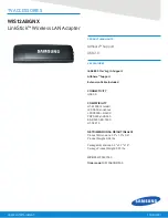
Figure C-3
SIMMs and NVSIMM
The system board has 16 SIMM sockets physically divided into two rows of
eight. The SIMMs are also logically divided into four groups of four, known as
group 0, 1, 2, and 3. Figure C-4 shows SIMM locations and identifies groups.
A system board can be installed with zero memory or from one to four groups
filled. For example, 0 SIMMs, 4 SIMMs, 8 SIMMs, 12 SIMMs or 16 SIMMs.
When installing memory, first install all group 0 SIMMs on all system boards,
from the lowest board slot number to the highest. Then, install group 1 SIMMs
in the same order, followed by groups 2 and 3 for the remaining SIMMs.
1
34
35
68
1
2
12
18
3
9
5
10
11
CBS
CBS
1
1
1
1
1
1
1
1
1
34
35
68
60P
63P
9P
13P
65P
67P
59P
4P
7P
1
1
1
1
1
1
1
1
1
CBS -
CBS -
1
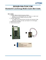
SIMM — Vendor 1
Capacity
Type
P/N
8 Mbyte
DRAM
501-1817
32 Mbyte
DRAM
501-2196
SIMM — Vendor 2
Capacity
Type
P/N
8 Mbyte
DRAM
501-1817
32 Mbyte
DRAM
501-2196
NVSIMM
Capacity
Type
P/N
1Mbyte
NVSIMM
501-2197
1
34
35
68
Battery
Summary of Contents for SunSwift SPARCserver 1000
Page 6: ...vi SPARCserver 1000 System Board Manual October 1994 ...
Page 10: ...x SPARCserver 1000 System Board Manual October 1994 ...
Page 14: ...xiv SPARCserver 1000 System Board Manual October 1994 ...
Page 20: ...1 6 SPARCserver 1000 System Board Manual October 1994 1 ...
Page 68: ...C 8 SPARCserver 1000 System Board Manual October 1994 C ...
Page 72: ...Index 4 SPARCserver 1000 System Board Manual October 1994 ...
Page 74: ...SPARCserver 1000 System Board Manual October 1994 ...