Chapter 4
Servicing Motherboard Components
4-15
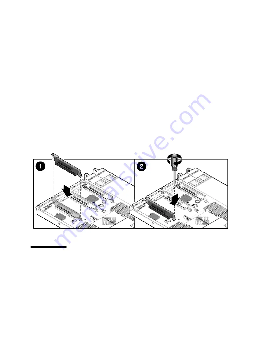
1. Lower the PCIe riser and any cards attached to it into the system.
2. Slide the back of the riser into the motherboard rear panel stiffener.
3. Install the screw that secures the riser to the motherboard (
FIGURE 4-8
).
4. Install the rear panel crossbar.
Slide the crossbeam down over the PCIe risers. The crossbar is secured with two
captive Phillips screws.
5. Slide the server into the rack. See
Section 6.3, “Returning the Server to the
Normal Rack Position” on page 6-4
.
6. Connect any data cables you removed to service the PCIe cards.
7. Reconnect the power cord (or cords) to the power supply (or supplies).
Verify that the AC Present LED is lit.
See
Section 6.4, “Powering On the Server” on page 6-5
.
FIGURE 4-8
Installing a PCIe Riser
4.4
Servicing PCIe Cards
The following topics are covered:
■
Section 4.4.1, “Sun Fire X4140 Server PCIe Card Guidelines” on page 4-16
■
Section 4.4.2, “Removing PCIe Cards” on page 4-17
■
Section 4.4.3, “Installing PCIe Cards” on page 4-18
Summary of Contents for Sun Fire X4140
Page 1: ...Sun Fire X4140 Server Service Manual Part No 820 2401 14 September 2010 Revision A...
Page 24: ...1 12 Sun Fire X4140 Server Service Manual September 2010...
Page 35: ...Chapter 2 Preparing to Service the System 2 11...
Page 36: ...2 12 Sun Fire X4140 Server Service Manual September 2010...
Page 94: ...4 40 Sun Fire X4140 Server Service Manual September 2010...
Page 126: ...6 6 Sun Fire X4140 Server Service Manual September 2010 FIGURE 6 5 Front Panel Power OK LED...
Page 140: ...C 4 Sun Fire X4140 Server Service Manual September 2010 FIGURE C 1 BIOS Utility Menu Tree...


