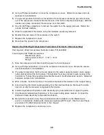
Troubleshooting
34
Problem
Possible Cause
Corrective Action
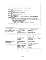
LCD reads Motor Temp-
ERR
Note: This fault is inferred
from detection of high return
pressure. Under normal
conditions, high return
pressure occurs only when
motor is not running.
Note: High return pressure
set point is 140 psig.
Compressor capsule
internal thermal protector
open
Low supply voltage
Excessive helium
charge pressure
Excessive operating
differential pressure
Insufficient cooling
water
Motor internal fault
High return pressure
Excessive helium
charge pressure
Insufficient differential
pressure
Return pressure transducer
fault
PCB 1 fault
Blown fuse (any)
Check mains voltage; correct if
outside the specifications.
See Specifications in Operating
Manual
See Specifications in Operating
Manual
Check coolant flow and
temperature; see Specifications in
Operating Manual
Check motor winding resistances.
See Specifications in Operating
Manual
See Specifications in Operating
Manual
See “Return Pressure Fault”
problem
Replace PCB 1
Check and replace fuse(s)
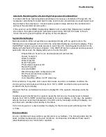
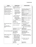
LCD reads Helium Temp-
ERR
Note: High helium
temperature set point is
93°C.
Insufficient cooling water
Blocked oil circulation
Temperature transistor fault
PCB 1 fault
Water flow is reversed
Check coolant flow and
temperature
See “Oil Level Fault” problem
Check that oil return capillary is
open; perform oil carryover
test.
Replace transistor
Replace PCB 1
Check installation of water lines
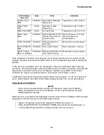
LCD reads Phase Seq-ERR
Reversed phase
Loss of phase
Blown fuse (any)
PCB 1 fault
Check mains power
Check mains power
Check and replace fuse(s)
Replace PCB 1
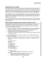
DB25 configuration fault
LCD reads DB-25
Config1-ERR
(or Config2-ERR)
Configuration selector
switch is in the wrong
position, or was in the
wrong position when
power was supplied.
Continuity value between
pins 7 and 8 is
not
compatible with DB25
configuration switch
setting.
PCB 1 fault
PCB 2 fault
Turn off power and move the
switch to the correct position.
See Tables 1 and 2 in the
Operating Manual
Replace PCB 1
Replace PCB 2
Summary of Contents for F-70H
Page 2: ......
Page 8: ...4 This page is intentionally blank...
Page 10: ...6 This page is intentionally blank...
Page 12: ...8 This page is intentionally blank...
Page 14: ...10 This page is intentionally blank...
Page 28: ...24 This page is intentionally blank...
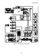
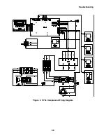
Page 40: ...Troubleshooting 36 Figure 4 F 70H Compressor Wiring Diagram...
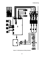
Page 41: ...Troubleshooting 37 Figure 5 F 70H Compressor Wiring Schematic...
Page 42: ...Troubleshooting 38 Figure 6 F 70L Compressor Wiring Diagram...
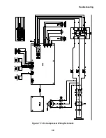
Page 43: ...Troubleshooting 39 Figure 7 F 70L Compressor Wiring Schematic...

