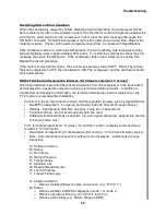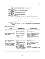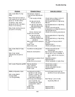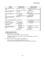
Troubleshooting
29
2.
Using a Phillips screwdriver, remove the compressor’s cover. Retain the screws and lock
washers for reinstallation.
3.
The gas temperature thermistor is fastened to the compressor discharge gas tube coming
out of the compressor head (located at the rear of the entire compressor package). With the
needle nose pliers, disconnect the two wires from the switch.
4.
Use the #0 Philips screwdriver to remove the switch from the supply gas tube. Retain the
screws and lock washers.
5.
Attach a replacement thermistor, using the hardware previously removed.
6.
Reattach the two wires to the terminals on the switch.
7.
Replace the compressor’s cover.
8.
Reconnect the power to the compressor.
Replace the Water High Temperature Thermistors (Thermistor Cable Assembly)
Part required: Water temperature thermistor cable, P/N 267039B
Tools required: #2 Phillips screwdriver
Needle nose pliers
Open-end wrenches 1", 1 1/8", 1 3/16"
Snoop
®
1.
Stop the compressor and disconnect the power to the compressor.
2.
Using a Phillips screwdriver, remove the compressor enclosure cover. Retain the screws
and lock washers for reinstallation.
3.
The water temperature thermistors are clipped to the water supply and water return copper
tubes directly behind the front panel. The adsorber must be removed to gain access to the
thermistors. Follow the procedure Adsorber Removal in the Maintenance section. Retain all
hardware and parts for reinstallation.
4.
With a marker, mark the location of the water temperature thermistors on the copper tubing.
5.
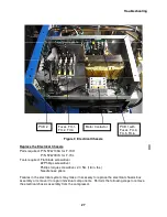
Disconnect the thermistor cable assembly from the electrical chassis. Remove the cable
ties and un-clip the two water temperature thermistors.
6.
Install a replacement thermistor cable assembly using new cable ties to support in place.
7.
Clip the water temperature thermistors to the copper tubing where marked. Connect the
thermistor cable assembly to the electrical chassis.
8.
Reinstall the adsorber, using the procedure Adsorber Installation in the Maintenance
section. Include leak checking the Aeroquip couplings with Snoop
®
. See the Leak Check
procedure in the Maintenance section in this manual.
9.
Replace the compressor’s enclosure cover.
Summary of Contents for F-70H
Page 2: ......
Page 8: ...4 This page is intentionally blank...
Page 10: ...6 This page is intentionally blank...
Page 12: ...8 This page is intentionally blank...
Page 14: ...10 This page is intentionally blank...
Page 28: ...24 This page is intentionally blank...
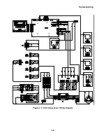
Page 40: ...Troubleshooting 36 Figure 4 F 70H Compressor Wiring Diagram...
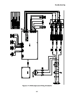
Page 41: ...Troubleshooting 37 Figure 5 F 70H Compressor Wiring Schematic...
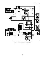
Page 42: ...Troubleshooting 38 Figure 6 F 70L Compressor Wiring Diagram...
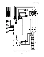
Page 43: ...Troubleshooting 39 Figure 7 F 70L Compressor Wiring Schematic...

