Maintenance
21
The flat gasket in the face of the Aeroquip male coupling seals the joint. A leak at this gasket
face seal can be detected only when a gas line is connected. A leak here can be caused by:
•
the coupling not fully tightened;
•
a worn, damaged, or missing gasket seal;
•
dirt on or under the gasket seal;
•
dirt on the female coupling’s mating surface;
•
damaged parts on either coupling which prevent proper mating or sealing.
Leak Repair
Leaks in flexible metal tubing cannot be repaired. Discard the damaged gas line and install a
new one.
Leaks at welded joints require special skills to repair. Consult a Service Center.
Replacing worn or damaged parts can repair leaks at the self-sealing couplings. Vent the
compressor before beginning to disassemble it.
Tightening the coupling frequently stops leaks at threaded joints. Continued leakage after
tightening requires coupling repair. Install new O-rings or Teflon tape as required.
Self-Sealing Couplings
From repeated connecting and disconnecting Aeroquip couplings, the gasket seal just inside the
face of the cold head gas supply and return male couplings may begin to leak and require
replacement. Damaged threads, leaking seals or a leaking poppet may require replacement of
coupling parts or of the complete coupling.
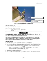
Replace the Gasket Seal
Part required: Gasket face seal, P/N 77002
Tools required: Needle or a narrow, flat blade screwdriver
Cotton swabs
Isopropyl alcohol
The gasket face seal on a self-sealing coupling is replaced while the gas line is disconnected
from the compressor or the cold head.
1.
Carefully pierce or pry the old gasket face seal and pull it from its recessed ring in the body
of the coupling. Discard the face seal.
2.
Using isopropyl alcohol on a clean, cotton swab, carefully remove any remaining adhesive
from the coupling’s recess. Avoid getting alcohol on the face of the poppet valve assembly.
3.
Dry the recessed surface with a clean, lint free cloth.
4.
Do not apply any adhesive
.
Press a new gasket seal into the recessed ring.
Summary of Contents for F-70H
Page 2: ......
Page 8: ...4 This page is intentionally blank...
Page 10: ...6 This page is intentionally blank...
Page 12: ...8 This page is intentionally blank...
Page 14: ...10 This page is intentionally blank...
Page 28: ...24 This page is intentionally blank...
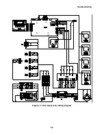
Page 40: ...Troubleshooting 36 Figure 4 F 70H Compressor Wiring Diagram...
Page 41: ...Troubleshooting 37 Figure 5 F 70H Compressor Wiring Schematic...
Page 42: ...Troubleshooting 38 Figure 6 F 70L Compressor Wiring Diagram...
Page 43: ...Troubleshooting 39 Figure 7 F 70L Compressor Wiring Schematic...

