Maintenance
22
Replace a Nylon Slide Rail
Part Required: Slide rail, P/N 267033B
Tool required: #2 Phillips screwdriver
NOTE
This procedure assumes that the compressor’s casters have been removed.
1.
Elevate the compressor for access to its bottom. Do not tip the compressor more than 10
degrees.
2.
Using a Phillips screwdriver, remove the three screws and lock washers that attach the slide
rail to the bottom panel of the compressor. Retain the screws and washers.
3.
Install a replacement slide rail using the hardware previously removed.
4.
Lower the compressor to rest on its slide rails.
Replace the Front Locator Plate
Part required: Front locator plate, P/N 300050C
Tool required: #2 Phillips screwdriver
1.
Using a Phillips screwdriver, remove the three screws and washers holding the front locator
plate to the compressor’s front panel. Remove the locator plate.
2.
Attach a new locator plate to the front panel using the previously removed screws and
washers.
Remove or Replace a Caster
Part required: Caster, P/N 49137
Tool required: Open-end wrench, 7 mm
AVOID EQUIPMENT FAILURE, CONTAMINATION OR A NUISANCE
SHUTDOWN.
Do not tip the compressor greater than 10 degrees from horizontal
to avoid flowing oil into unwanted places.
1.
Stop the compressor and disconnect the power to the compressor. It is not necessary to
remove the compressor’s cover.
2.
Elevate and support the compressor base about 3 ½” to 4” (90 to 100 mm) above the work
surface. Do not tip the compressor more than 10 degrees.
3.
Using a 7 mm open-end wrench on the flat of the caster’s stem, turn the stem to remove it
from the nut inside the compressor’s base. Continue to remove the other casters.
4.
Install new casters if required, using the 7 mm wrench.
5.
Lower the compressor to rest on either its casters or its Nylon slide rails.
6.
Reconnect the power to the compressor.
Summary of Contents for F-70H
Page 2: ......
Page 8: ...4 This page is intentionally blank...
Page 10: ...6 This page is intentionally blank...
Page 12: ...8 This page is intentionally blank...
Page 14: ...10 This page is intentionally blank...
Page 28: ...24 This page is intentionally blank...
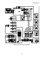
Page 40: ...Troubleshooting 36 Figure 4 F 70H Compressor Wiring Diagram...
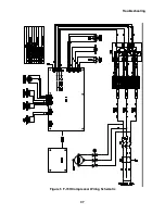
Page 41: ...Troubleshooting 37 Figure 5 F 70H Compressor Wiring Schematic...
Page 42: ...Troubleshooting 38 Figure 6 F 70L Compressor Wiring Diagram...
Page 43: ...Troubleshooting 39 Figure 7 F 70L Compressor Wiring Schematic...

