16
Operation & Maintenance Manual
Cyclo® HBB
Cyclo® HBB
3
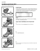
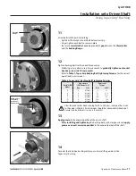
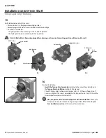
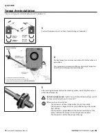
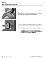
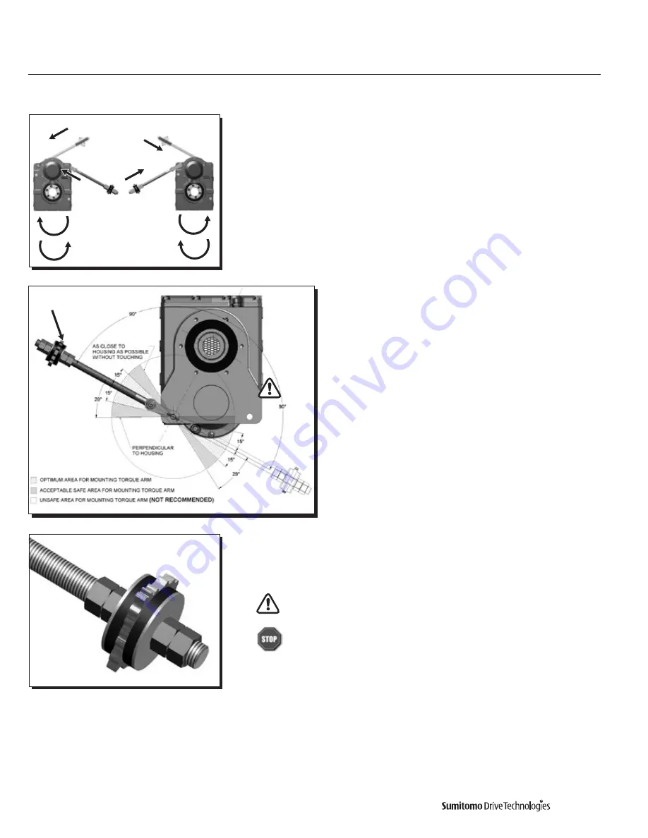
Position the torque arm so it will be in tension during unit operation
4
Position Torque Arm as close as possible to 90° relative to the unit
output bore
Sumitomo does not recommend the use of multiple Torque Arm
Assemblies to achieve greater overall length
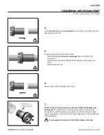
5
After inserting the torque rod into the mounting surface, carefully tighten nuts on
either side of torque rod
Do Not over tighten nuts
Tighten to point where rubber bushings can still
be hand rotated when the unit is turned off
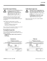
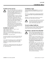
Before starting unit, verify that:
• The torque arm will be in tension when the unit is operating.
• The torque arm is aligned with the Cyclo® HBB housing when viewed
from the side
• The torque arm is perpendicular to the line between the axis of the
output shaft and the torque arm’s housing connection point
• The torque arm is not touching the gear housing.
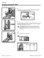
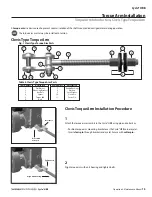
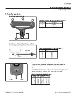
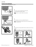
Torque Arm Installation
Clevis Torque Arm Installation Procedure
CW Shaft
Rotation
CCW Shaft
Rotation
CCW Shaft
Rotation
CW Shaft
Rotation
Customer Mounting
Surface
Summary of Contents for Cyclo HBB
Page 1: ...0 7 6 0 1 6 0 0 0 3 H B B O M2 0 1 8...
Page 27: ...MA X MI N...


