Cyclo® HBB
Operation & Maintenance Manual
9
Cyclo® HBB
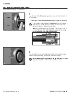
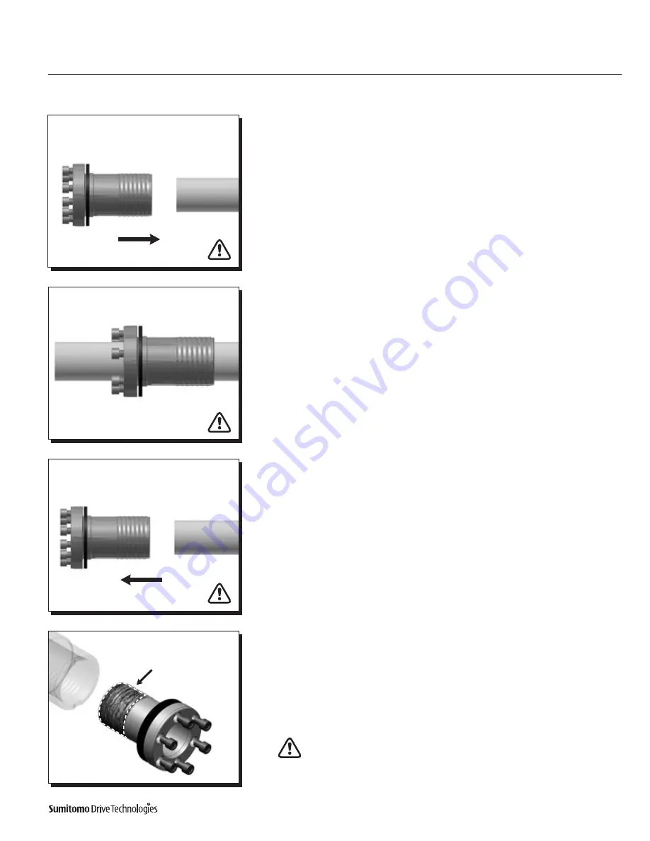
Installation onto Driven Shaft
Using Taper-Grip® Bushing
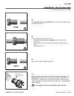
4
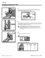
Clean all
grease, oil
and/or
anti-seize paste
from the driven shaft Slide Taper-Grip®
bushing onto driven shaft
5
Inspect and test Taper-Grip® Bushing on shaft
• Check shaft for
burrs, corrosion, or warpage
Repair or replace shaft
as necessary
• Slide bushing back and forth along shaft, checking for surface irregularities
and fit
• Verify bushing bore size.
6
Remove Taper-Grip® Bushing from driven shaft
7
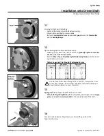
Apply a thin layer of anti-seize paste to the male threads of the Taper-Grip®
bushing only
Ensure that the anti-seize paste does not enter the Taper-Grip®
bushing bore Carefully thread the Taper-Grip bushing into the hub of the speed
reducer or gearmotor until the thrust collar solidly engages the unit hub surface and
the bushing flange
Do not apply anti-seize paste to the female threads in the hub
Apply thin layer of
anti-seize paste to male
threads of bushing only
Summary of Contents for Cyclo HBB
Page 1: ...0 7 6 0 1 6 0 0 0 3 H B B O M2 0 1 8...
Page 27: ...MA X MI N...


