Troubleshooting Guides
Integrated
(700-
3
BASE)
Series
8-16
#3758424 - Revision B - December, 2005
700BR-3
X” vacuum to X psi
XX psi to XXX psi
700BF/I-3
3” vacuum to 2 psi
90 psi to 120 psi
SEALED SYSTEM TROUBLESHOOTING / DIAGNOSTICS TABLES
Before tapping into the sealed system to check pressures, see General Troubleshooting Guide, taking note of prob-
lems “A” through “J”, and if applicable, be sure to reference the “Pointers” in the first column. By initiating Diagnostic
Mode and observing evaporator temperatures, it may be determined unnecessary to tap the sealed system. If need-
ed, the table on the following page provides a quick reference for temperature/pressure correlation.
NOTE:
If entering the sealed system to check pressures, always use solder-on process valves. Do NOT use bolt-
on process valves as they are prone to leak.
NOTE:
Whenever servicing the sealed system, the high-side filter-drier must be replaced.
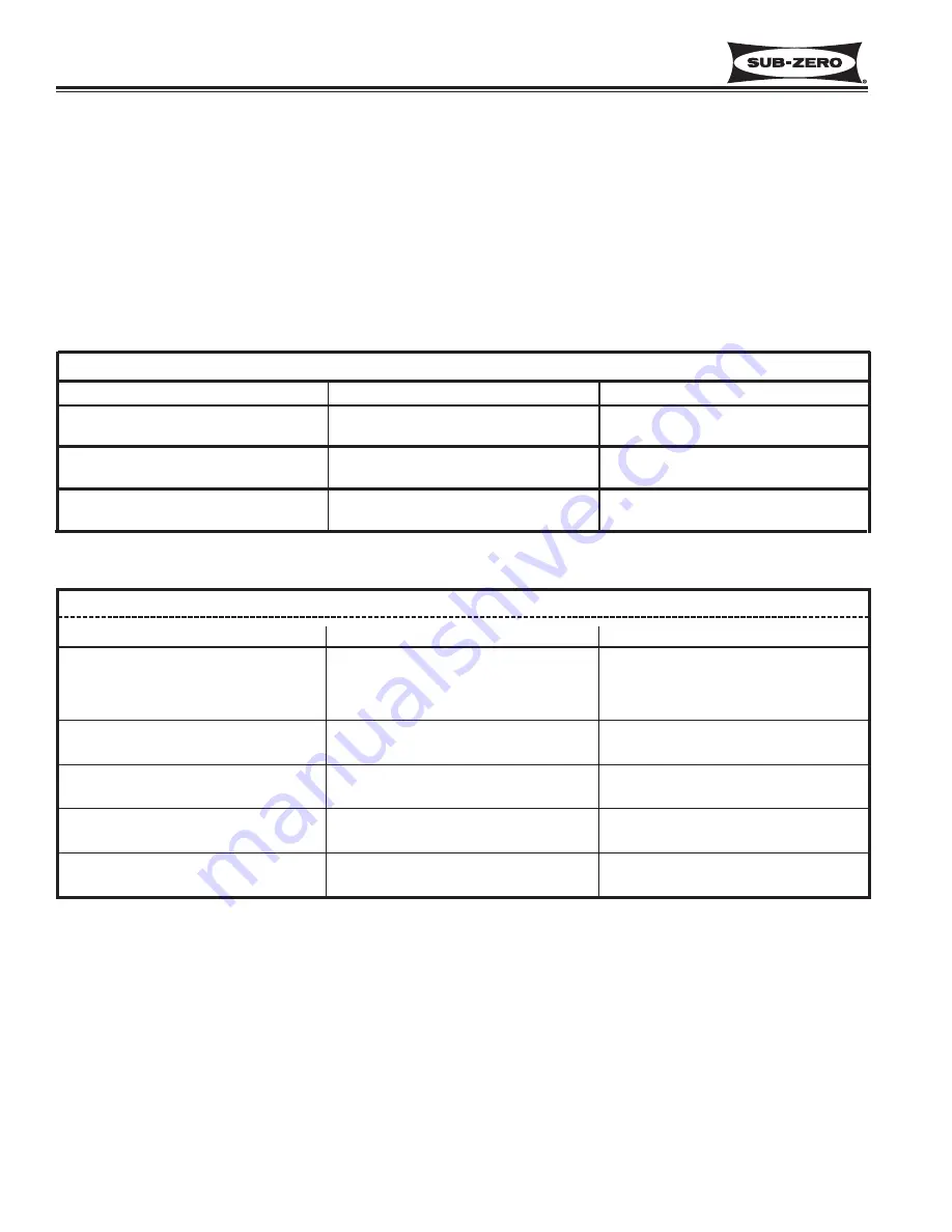
NORMAL OPERATING PRESSURES
PRESSURE INDICATIONS
If low-side pressure is
NORMAL
LOW
LOW
HIGH
HIGH
& high-side pressure is
NORMAL
LOW
HIGH
LOW
HIGH
possible problem is
MECHANICAL
(see General Troubleshooting Guide)
LEAK
RESTRICTION
INEFFICIENT COMPRESSOR
OVER CHARGE
Model
Normal Low-Side Pressures
Normal High-Side Pressures
700BC/I-3
3” vacuum to 2 psi
90 psi to 120 psi
Summary of Contents for 700-3 BASE
Page 2: ......
Page 12: ...Installation Information Integrated 700 3 BASE Series 2 4 3758424 Revision B December 2005 ...
Page 40: ...Electronic Control System Integrated 700 3 BASE Series 3 28 3758424 Revision B December 2005 ...
Page 48: ...Sealed System Information Integrated 700 3 BASE Series 4 8 3758424 Revision B December 2005 ...
Page 52: ...Airflow Fan Blade Spacing Integrated 700 3 BASE Series 5 4 3758424 Revision B December 2005 ...
Page 58: ...Icemaker Information Integrated 700 3 BASE Series 6 6 3758424 Revision B December 2005 ...
Page 114: ...Wire Diagrams Schematics Integrated 700 3 BASE Series 10 10 3758424 Revision B December 2005 ...


